Do you have a question about the Lakeshore 240 Series and is the answer not in the manual?
Details the warranty terms and conditions for Lake Shore products.
General safety precautions and hazard symbols for operating the instrument.
Wiring for power and setting up PROFIBUS-DP communication.
Connecting and configuring diode and resistor sensor inputs.
Detailed steps for configuring the module using MeasureLINK software.
Configuration and communication using the PROFIBUS-DP protocol.
How to communicate and control the module using a USB connection.
Steps for resolving issues with the USB interface connection.
List and explanation of common error messages displayed by the module.
| Temperature Resolution | 0.001 K |
|---|---|
| Sensor Excitation | 10 μA to 10 mA, programmable |
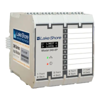
| Display | Backlit LCD |
| Computer Interface | RS-232 |
| Sensor Types | diode, thermocouple |
| Communication Interface | RS-232 |
| Power Supply | 100-240 VAC, 50/60 Hz |
| Dimensions | 89 mm × 213 mm × 381 mm (3.5 in × 8.4 in × 15 in) |