Do you have a question about the Lancair Columbia 400 and is the answer not in the manual?
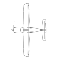
Overview of the handbook's content, including FAA regulations and manufacturer information for the Columbia 400.
Details on the airplane's engine, propeller, fuel, and oil specifications, including capacities and grades.
Definitions and explanations of terms, symbols, and abbreviations used in the manual for clarity.
Information on manual conventions, including use of terms like Warning, Caution, Note, and meanings of specific phrases.
Tables and graphs for converting US weights and measures to metric and imperial equivalents for pilot convenience.
Overview of Section 2, detailing operating limitations, instrument markings, and placards for safe airplane operation.
Specifies airspeed limitations based on gross takeoff weight, including maneuvering, flap extended, and never exceed speeds.
Explanation of colored arcs and bands on the airspeed indicator and their significance for flight operations.
Details limitations for the engine, including manufacturer, power settings, temperatures, pressures, and approved fuel grades.
Information on recommended oil grades for temperature ranges, oil temperature, oil pressures, approved fuel grades, and fuel flow.
Specifies propeller diameters, blade angles at 30 inches station pressure, and low/high pitch settings.
Defines maximum ramp, empty, takeoff, landing weights, and maximum baggage weight for the airplane.
Specifies the center of gravity limits for utility category operations and the linear variation between datum points.
Details limitations for maneuvers, including approved acrobatic maneuvers and spin prohibitions.
Maximum flight load factors for utility category operations, specified for flaps up and flaps down configurations.
States the limitation regarding flight into known icing conditions.
Details limitations for electronic displays like EX5000 MFD and Garmin GNS 430, specifying approved usage and conditions.
Information about placards displayed on the interior and exterior of the airplane for operational importance.
Explains the importance of emergency procedures and encourages pilots to tabulate them for flight conditions.
Lists recommended airspeeds for various emergency operations like engine failure and precautionary landings.
Provides detailed, step-by-step checklists for various emergency situations, including engine failures and system malfunctions.
Expands on emergency procedures, providing detailed explanations and considerations for specific situations.
Introduces normal procedures and checklists, encouraging pilots to tabulate them for flight conditions.
Provides a general overview of indicated airspeeds for normal operations based on gross weight and flap settings.
Detailed checklists for normal operations, covering preflight, engine start, taxi, takeoff, climb, cruise, descent, and landing.
Provides amplified discussions on specific normal procedures, including preflight checks, fuel system, and engine instruments.
Discusses the special techniques required for crosswind takeoffs and landings, referring to amplified discussions.
Details recommended airspeeds and power settings for normal climbs, including best rate and angle of climb.
Covers considerations for cruise flight, including flight planning, power settings, mixture adjustments, and altitude.
Describes considerations for descent, including gradual power reductions, mixture adjustments, and speed brake usage.
Checklist items to be performed before landing, including securing seat belts, setting mixture, and checking flaps.
Procedures for normal landings, covering approach speed, touchdown, landing roll, and braking.
Procedures for short field landings, emphasizing landing just past the runway beginning at minimum speed.
Steps for initiating a go-around, including maximizing power, minimizing drag, and establishing a climb.
Procedures for engine shutdown after landing, including idling for turbocharger cooling and final switch settings.
Information on stall characteristics and recovery procedures, including unaccelerated and accelerated stalls.
Overview of performance charts and graphs designed to assist pilots in determining flight characteristics.
Table showing calibration errors between indicated and calibrated airspeeds for normal and alternate static sources.
Calibration chart showing the relationship between calibrated and equivalent airspeeds at 12,000 ft.
Calibration chart showing the relationship between calibrated and equivalent airspeeds at 18,000 ft.
A graph illustrating the relationship between Fahrenheit and Celsius temperatures for conversions.
Tabulated stall speeds for various flap settings and angles of bank at maximum gross weight and forward CG.
Performance changes that may result from SpeedBrakes deployment during takeoff, cruise, and stall conditions.
Table used to determine headwind, crosswind, or tailwind components based on wind angle and velocity.
Chart for determining takeoff distance, including ground roll and obstacle clearance, based on associated conditions.
Chart used in conjunction with takeoff distance to determine proper takeoff speed based on aircraft weight.
Table showing maximum rate of climb in feet per minute for various pressure altitudes, weights, and temperatures.
Table providing information to estimate climb times, fuel used, and distance traveled to a specific altitude.
Overview of cruise data tables, explaining tabulation for altitude increments and ranges, and proper leaning techniques.
Demonstrates how to solve for takeoff ground run, total takeoff distance, fuel used for climb, and other performance calculations.
Overview of Section 6, covering weight and balance procedures, equipment lists, and pilot-specific loading procedures.
Detailed procedures for determining the airplane's empty weight and center of gravity, including configuration and leveling.
Procedures for determining gross weight and loaded CG, covering useful load, stations, baggage, and computations.
Details the airplane's weight limitation (3600 lbs) and balance/CG range requirements for safe flight.
Lists other weight limitations, including minimum flying weight and maximum zero fuel weight, with variations.
Specifies the maximum empty weight and its practical applications, including calculating maximum additional equipment weight.
Explanation of install codes 'B' (Basic) and 'O' (Optional) for equipment installed in the airplane.
Corresponds equipment list chapters to maintenance manual chapters for part maintenance information.
Identifies minimum equipment required for IFR and night operations, indicated by shaded boxes.
Recommends headset use for comfort and communication, noting they are optional and pilot-provided.
Lists equipment installed in the aircraft and their requirements for different flight operations (All, Night, IFR, Opt.).
A detailed list of installed equipment, including item numbers, drawing references, weights, and arms from the datum.
Overview of Section 7, covering the airplane's airframe, powerplant, systems, avionics, and components.
Describes the airplane's construction techniques, including fuselage, wings, fuel tanks, and horizontal stabilizer.
Details the construction and operation of the airplane's flight controls: ailerons, elevator, rudder, and servo tabs.
Illustrates the flight control system, showing linkages, rods, bellcranks, and control surfaces.
Discusses the lack of an integrated control lock and aftermarket options, advising against certain techniques.
Explains the two-axis trimming system for elevator and aileron, including controls, indicators, and runaway procedures.
Diagram identifying instruments and controls in the instrument panel and cockpit layout.
Describes the electric Fowler-type flaps, their operation, switch positions, and extension speed placards.
Details the main and nose landing gear, including construction, tires, brakes, and nose wheel operation.
Describes the front and rear seats, including adjustability, materials, and energy-absorbing foam for protection.
Explains the integrated three-point restraint system, its use, adjustment, and inertial reel locking mechanism.
Describes the gull wing cabin doors, their operation, hinges, latching mechanism, and door locks.
Details the pneumatic door seal system, its operation, components, and potential failures.
Explains the hydraulic braking system, including rudder pedal master cylinders, brake housing, and disc brakes.
Describes directional control through differential braking and considerations for maintaining forward momentum.
Provides information on engine specifications, turbochargers, engine controls (throttle, propeller, mixture), and sub-systems.
Covers basic avionics installation and optional items, focusing on the Avidyne FlightMax EX5000 MFD.
Explains controls for the map page, including sensor modes, mapping functions, orientation, declutter, and range.
Describes the Trip Page functionality, including distance, time, waypoints, and METAR information.
Details the NRST page functionality, showing nearest airports, VORs, NDBs, intersections, and obstacles.
Provides access to Normal checklists by phase of flight, allowing sequencing and marking of completed steps.
Accesses complete Emergency checklists with one-button selection for Ground, In-Flight, Landing, and System Malfunctions.
Explains the datalink system, including NEXRAD, METARs, AIRMETs/SIGMETs, TFRs, and their display on the MFD.
Describes the Map page as the primary display for datalink weather, including NEXRAD, lightning, and METAR symbols.
Details Multilink setup and features, including backup, expanded coverage, messaging, and flight tracking.
Describes the Engine page on the MFD, covering gauges, electrical system, OAT, fuel, and cylinder temperatures.
Provides instructions for leaning the mixture for best economy using TIT values, between 40% and 65% power.
Explains how engine instrument data blocks can be configured on the Map page for lean status and graphical representation.
Describes Aux Pages for setting user preferences and sensor settings, including Message List, Setup Menu, and Datalink.
Allows setting criteria for nearest airport searches, including type, surface, and minimum runway length.
Defines navigation symbols and default display settings for the Declutter button, with IFR/VFR defaults.
Allows editing data blocks in the Map Page corners to display information from available data types.
Enables setting the time source, date, time zone offset, and menu timeout preferences.
Configures datalink preferences, including enabling Narrowcast, Broadcast, and Multilink systems.
Overview of the audio panel system, including its general functions, abnormal procedures, and fail-safe features.
Details the GPS navigation system, its capabilities, accuracy specifications, and abnormal operation procedures.
Describes the GTX 330 transponder, including mode selection, code selection, and other functions.
Overview of the rate autopilot system, its functions, modes, and interaction with the PFD and Garmin GNS 430.
Details the SpeedBrake system, its components, operation, and warnings related to icing or deployment.
Describes the carbon monoxide detector, its installation, activation, and the visual/aural alerts it provides.
General description of the TCAD system for identifying potential collision threats and displaying traffic information.
Explains how traffic information is provided by TCAD and TIS systems, including symbols and modes of operation.
Defines the three advisory levels: Traffic Advisories (TA), Proximate Advisories (PA), and Other Traffic (OT).
Explains the audible voice annunciation provided by the TCAD for traffic alerts, including clock position and relative altitude.
Describes the dual function of the Acknowledge/Traffic button for muting TA announcements and acknowledging alerts.
Refers to the Avidyne Flightmax EX5000 MFD section for details on TCAD display.
Covers procedures for ground handling, routine care of interior/exterior, maintenance intervals, publications, and servicing.
Details Lancair Advisory Service, customer delivery package, fuel servicing, and oil servicing procedures.
Covers airplane inspection periods, airworthiness directives, preventive maintenance, alterations, and required inspections.
Provides procedures for ground handling, towing, parking, securing the airplane, and storage categories.
Instructions for exterior and interior cleaning and care, including paint protection and windshield maintenance.
Guidelines for engine cleaning and care, including oil changes, air filter replacement, and propeller cleaning.
Information about optional equipment installed via Supplemental Type Certificate (STC) and their AFM/POH supplements.
A table for recording the installation of after-market supplemental equipment and devices with their STC information.
| Manufacturer | Lancair |
|---|---|
| Model | Columbia 400 |
| Type | Light Aircraft |
| Category | General Aviation |
| Seating Capacity | 4 |
| Engine | Continental TSIO-550-C |
| Service Ceiling | 25, 000 ft (7, 620 m) |
| Maximum Takeoff Weight | 3, 600 lb (1, 633 kg) |
| Horsepower | 310 hp |
| Max Speed | 235 knots (435 km/h, 270 mph) |
| Wingspan | 36 ft (11 m) |
| Height | 9 ft (2.7 m) |
| Fuel Capacity | 98 US gallons (371 L) |
| Range | 1, 200 nautical miles (1, 380 mi, 2, 220 km) |