11
Operations
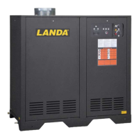
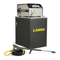
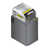
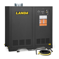
Component Identification - All Models
Pump — Delivers a specific gpm to the high pressure
nozzle which develops pressure. (Not Shown)
Spray Gun — Controls the application of water and
detergent onto cleaning surface with trigger device.
Includes safety latch.
Detergent Valve— Allows you to siphon and mix
detergents.
Wand — Must be connected to the spray gun.
High Pressure Hose — Connect one end to water
pump high pressure discharge nipple and the other end
to spray gun.
Rupture Disk — Secondary pressure release in the
unlikely event the unloader valve fails. (Not Shown)
Unloader Valve — Safety device which, when the
spray gun closes, prevents over pressurization. (Not
Shown)
NOTE: If trigger on spray gun is released for more
than 3 minutes, water will leak from the pump
protector. Warm water will discharge from pump
protector onto floor. This system prevents internal
pump damage.
Landa ENG Operator’s 9.801-511.0 - F
GR
O
U
ND
8
1
0
1
2
1
4
1
6
0
2
4
6
T
A
C
H
/
H
O
U
R
T
A
C
H
/
H
OU
R
1
.
P
lac
e
al
l
s
wi
tc
he
s
in
th
e
“OFF
”
p
o
s
i
t
i
o
n
.
2
.
Co
n
n
e
c
t
p
o
w
e
r
s
u
p
p
ly
to
p
ro
p
e
r
l
y
g
r
o
u
n
d
e
d
o
u
t
le
t
.
T
e
s
t
th
e
GFCI
(if
e
qu
ip
p
e
d
)
u
s
i
n
g
th
e
r
es
e
t
a
n
d
t
e
s
t
p
r
o
c
edu
r
e
s
pr
o
v
id
e
d
o
n
th
e
G
F
C
I
de
v
ic
e
.
Th
e
GFC
I
m
u
st
b
e
res
e
t
a
n
d
t
e
s
t
e
d
w
it
h
e
v
e
r
y
us
e
.
3
.
S
e
c
u
r
e
h
igh
p
re
s
s
ur
e
ho
s
e
,
s
hut
-
off
gu
n
a
n
d
w
a
n
d
to
o
u
t
-
le
t
4.
Co
n
n
e
c
t
w
at
e
r
su
pp
l
y
h
o
s
e
a
n
d
tu
r
n
on
w
a
te
r
.
5.
Gras
p
w
a
n
d
P
lac
e
p
um
p
s
w
itch
i
n
th
e
“
O
N”
p
o
si
t
io
n
.
6.
T
u
r
n
g
a
s
v
a
lv
e
c
o
n
t
ro
l
k
nob
to
“
O
N”
p
os
i
t
io
n
.
P
ilo
t
wi
ll
l
ig
h
t
a
ut
om
a
ti
ca
l
ly
w
h
en
bu
r
n
e
r
s
w
it
c
h
i
s
tu
r
n
e
d
“
ON
”
.
7
.
T
o
he
a
t
w
a
te
r
,
p
lac
e
bu
r
n
e
r
s
w
it
ch
in
th
e
“
O
N
”
p
o
si
t
i
o
n
a
n
d
a
d
jus
t
t
he
r
mostat
to
d
e
sir
ed
t
e
mpe
ra
t
ur
e.
8.
T
u
r
n
on
d
e
t
e
r
gen
t
a
n
d
p
r
oce
e
d
wi
th
c
l
e
a
ni
n
g
.
9.
A
fte
r
c
le
a
n
ing:
A
.
T
u
r
n
of
f
d
et
e
r
g
en
t
a
nd
r
i
ns
e
.
B
.
P
lace
b
u
r
n
er
s
w
itch
in
th
e
“
O
F
F
”
po
sition.
C.
A
llo
w
m
ac
hi
n
e
to
d
is
c
h
ar
g
e
w
a
t
e
r
f
or
2
-
3
m
i
nu
t
e
s
to
c
o
ol
c
oil
.
D
.
P
lac
e
p
u
mp
s
w
itc
h
i
n
th
e
“
O
FF”
p
osit
io
n
.
E
.
Squee
z
e
tr
i
g
ge
r
gu
n
to
r
e
l
i
e
v
e
s
ys
te
m
p
re
ss
u
r
e
.
F
.
T
u
r
n
of
f
w
a
te
r
s
up
pl
y.
MODE D’EMPLOI
L
IRE
LE MANU
EL DE
L
’
OP
ER
A
TE
UR
A
V
AN
T UTILIS
A
T
I
O
N
U
N
E
M
A
UV
AIS
E UTILIS
A
T
I
O
N
P
EU
T
C
A
U
S
E
R
DE
S
BL
E
S
SURE
S
O
U
D
OMM
A
G
E
S
M
A
T
É
RIE
L
S
.
I
NST
R
U
CCIONES
DE OPE
R
A
C
IO
N
LE
A
EL
MANU
A
L
D
E
O
P
E
R
A
C
IÓ
N
A
N
TE
S DE
U
S
A
R
S
E.
L
A
OPER
A
C
I
Ó
N
I
N
A
D
E
C
U
A
D
A
P
U
ED
E
O
C
AS
I
O
NA
R
LE
SI
ON
ES
P
ERSON
ALE
S
O
D
A
Ñ
O
S
A
L
AS
PR
O
P
IE
D
AD
E
S
.
OPER
A
T
I
N
G
INST
RU
CTI
ONS
REA
D
O
PE
R
A
T
I
N
G
M
A
N
U
A
L
B
E
F
OR
E
O
P
ER
A
T
I
N
G
M
A
C
HI
N
E
.
I
M
P
R
O
P
E
R
OPE
R
A
T
I
O
N
M
A
Y
RE
S
U
L
T
I
N
PE
RSONAL
I
N
J
U
R
Y
O
R
PR
O
P
E
R
T
Y
D
AM
A
GE
.
1
.
Co
l
o
que
t
o
do
s
l
os
in
t
er
r
u
p
t
o
r
e
s
e
n
la
p
o
s
ici
ó
n
“
O
F
F
”
(
A
P
A
G
A
DO
)
.
2
.
C
o
n
e
c
t
e
la
fu
ent
e
de
en
e
rg
í
a
a
un
t
o
mac
or
r
i
e
n
t
e
co
ne
cta
d
o
a
ti
e
r
r
a
d
e
m
odo
ad
-
ec
ua
do
.
P
r
u
e
b
e
el
I
nte
rr
u
p
to
r
A
ccio
na
d
o
p
o
r
C
o
r
r
i
e
n
t
e
d
e
Pérd
id
a
a
T
i
e
r
r
a
(
G
FC
I
p
o
r
s
u
s
s
i
gl
a
s
e
n
In
gl
é
s
)
(s
i
h
u
bier
a
)
m
edi
a
nt
e
l
o
s
p
ro
c
edi
m
i
e
nto
s
d
e
re
in
ic
i
o
y
pr
u
e
b
a
in
c
o
rp
o
r
a
d
o
s
e
n
dich
o
disposit
i
v
o
.
E
l
G
F
CI
d
eb
e
r
e
i
nic
ia
r
s
e
y
p
o
n
e
r
s
e
a
p
r
u
eb
a
cada
v
e
z
qu
e
se
us
e
.
3
.
Aseg
u
r
e
la
ma
ng
u
e
r
a
d
e
alta
pr
e
s
ió
n
,
pi
sto
l
a
y
v
a
r
ill
a
al
ac
opl
a
do
r
d
el
t
om
ac
or-
r
i
e
n
t
e
.
4.
C
o
n
e
c
t
e
la
m
a
n
g
u
e
r
a
de
s
u
m
i
n
ist
r
o
de
ag
u
a
y
a
b
ra
la
l
l
a
v
e
.
5.
S
u
j
e
t
e
la
v
a
r
il
l
a
.
C
ol
o
que
e
l
i
n
t
e
rr
u
pt
o
r
d
e
l
a
b
o
m
b
a
e
n
la
p
o
s
i
ci
ó
n
“
O
N”
(EN
CEND
ID
O
)
.
6.
C
o
l
o
q
u
e
la
pe
r
il
la
de
c
o
n
t
ro
l
de
la
válvul
a
de
g
as
en
la
po
s
i
c
ió
n
“
ON
”
(
ENC
END
I
-
DO
)
.
E
l
p
il
o
to
s
e
e
n
c
e
n
d
e
r
á
a
u
t
o
m
á
ti
c
a
m
e
n
t
e
cu
a
n
d
o
e
l
q
ue
m
a
d
o
r
s
e
e
n
c
ie
n
d
a
.
7.
A
de
c
al
e
n
t
a
r
el
ag
ua
,
co
lo
q
u
e
e
l
in
t
er
r
u
pt
o
r
d
el
q
u
ema
d
o
r
e
n
l
a
p
os
i
c
i
ó
n
“
O
N”
(
EN
CEN
DI
DO
)
y
a
j
u
s
te
e
l
t
e
r
m
ostato
a
la
t
e
mp
er
a
tu
r
a
de
s
e
a
d
a
.
8
.
Encien
d
a
el
d
et
e
rg
e
nt
e
y
pr
oc
ed
a
co
n
la
li
m
p
ie
z
a.
9.
D
esp
u
é
s
d
e
l
impi
ar
:
A
.
Ap
a
gu
e
el
d
e
ter
g
en
te
y
en
ju
a
gu
e
.
B
.
P
o
n
g
a
e
l
int
e
rr
up
to
r
de
l
q
uem
a
d
o
r
e
n
la
p
o
s
ici
ó
n
“
O
F
F”
(A
P
A
GA
D
O
)
.
C
.
De
j
e
q
u
e
l
a
m
á
qu
in
a
d
e
sc
a
r
gu
e
a
g
u
a
po
r
2
ó
3
mi
n
u
t
o
s
p
a
r
a
q
u
e
s
e
en
f
rí
e
el
s
e
r
p
e
ntí
n
.
D
.
P
o
n
g
a
el
i
n
ter
r
u
p
t
o
r
de
l
a
b
o
m
ba
en
la
po
sici
ó
n
“
O
FF
”
(
A
P
A
G
AD
O
)
.
E
.
P
r
e
s
ione
la
p
is
t
o
l
a
p
ar
a
a
liv
i
a
r
la
pre
s
ión
de
l
s
is
t
e
ma.
F
.
C
ie
r
re
el
suminis
tro
d
e
ag
ua
.
1.
M
et
t
e
z
t
o
u
s
les i
nt
er
rup
t
e
u
r
s
en
p
o
s
i
t
io
n
“O
FF
”
.
2.
C
o
n
ne
c
t
e
z
le
b
l
oc
d’
a
lim
e
nt
a
t
i
on
éle
c
t
r
i
qu
e
à
u
n
e
p
r
i
se
co
rre
c
t
em
e
n
t
m
is
e
à
l
a
t
e
rr
e
.
T
es
t
e
z
le
d
isj
o
nc
t
e
u
r d
e
fu
i
t
e
d
e
t
e
r
r
e
(
l
e
c
a
s
éc
hé
an
t
)
à
l’a
id
e
d
e
s
p
ro
c
é
du
r
es
d
e
réi
n
it
i
a
l
i
s
at
io
n
e
t
d
’e
s
s
a
i
i
n
d
i
q
u
ée
s
s
u
r
le
d
i
s
jo
n
c
t
e
u
r
.
L
e
di
s
jo
nc
t
e
u
r
d
o
it
ê
tr
e
r
éin
iti
alisé
e
t
t
e
s
t
é
à
c
h
a
q
ue
utili
-
sa
ti
on.
3.
F
i
x
e
z
l
e
tu
y
a
u
à
ha
ut
e
p
re
s
s
ion
,
le
p
is
tol
e
t
e
t
le
t
u
b
e
r
i
g
id
e
au
r
a
c
c
o
r
d
d
e
s
o
rt
i
e
.
4
.
Co
n
n
ec
te
z
le
tu
y
a
u
à
e
au
e
t
f
a
it
e
s
c
ou
l
e
r
l’
e
a
u
.
5
.
T
e
n
e
z
le
t
u
be
r
i
g
id
e
f
e
rm
e
m
e
n
t
.
M
ett
e
z
l
’i
n
te
r
r
u
p
t
eu
r
d
e
la
po
m
p
e
e
n
p
o
s
it
i
o
n
“
O
N
”
.
6.
T
o
u
r
ne
z
le
b
o
u
to
n
du
r
o
b
ine
t
de
ga
z
e
n
po
si
t
i
o
n
“
ON
”
.
L
a
v
e
ille
u
s
e
s’
allume
au
to
m
a
t
iq
u
e
men
t
lo
rs
qu
e
l
’int
e
r
r
up
t
e
u
r
du
b
r
ûle
u
r
es
t
mi
s
s
u
r
“
O
N
”
.
7.
P
o
u
r
ch
auf
f
e
r
l’e
a
u
,
m
et
t
ez
l’i
n
t
e
r
r
up
te
u
r
du
b
rû
le
u
r
s
u
r
“
O
N
”
e
t
r
ég
lez
le
t
h
e
r
m
o
st
a
t
à
la
t
e
m
pé
ra
tu
r
e
v
ou
lue
.
8
.
A
c
t
iv
e
z
l
e
d
é
t
e
r
ge
nt
e
t
c
o
m
m
e
n
c
ez
l
e
n
e
t
t
o
y
a
ge
.
9
.
A
pr
è
s
l
e
n
et
t
o
ya
g
e
:
A
.
C
o
upe
z
le
d
ét
e
r
ge
nt
et
r
i
n
c
ez
.
B
.
M
e
t
t
e
z
l’in
t
e
r
r
up
te
u
r
du
b
r
û
le
u
r
s
u
r
“O
FF
”
.
C
.
La
iss
ez
la
m
a
c
h
i
n
e
é
v
ac
ue
r
l’e
a
u
p
end
a
n
t
2
à
3
m
i
n
u
t
e
s
,
le
t
e
mp
s
qu
e
la
b
o
b
i
n
e
r
ef
r
o
idi
s
s
e
.
D
.
Me
tt
ez
l’
int
e
r
r
up
te
u
r
de
la
po
m
p
e
s
u
r
“
OFF”.
E
.
A
c
ti
o
n
ne
z
l
e
p
ist
ol
et
p
o
ur
r
é
d
uir
e
la
pr
e
ss
i
on
d
u
sy
s
tè
m
e
.
F
.
Co
up
ez
l’
ea
u
.
WAR
N
ING
PR
EC
A
U
CI
ON
/
A
V
ER
TIS
SEME
N
T
T
O
RE
D
U
CE
THE RI
S
K
O
F I
N
J
UR
Y
R
E
A
D
OPE
R
A
T
OR
’
S
M
A
N
U
A
L
C
A
RE
F
U
L
L
Y
B
E
FO
R
E
US
I
NG
.
T
H
IS MA
C
H
I
N
E
T
O
B
E
USE
D
ON
L
Y
BY
Q
U
ALIFIED
OPER
A
T
O
RS
.
L
E
A
EL
MA
N
U
A
L
OP
ER
A
CION
ANTE
S
DE
USARSE.
ESTE
E
Q
U
I
P
O
DE
BE
SER
USAD
O
SO
LA
MENTE
PO
R
OP
ERA
-
D
ORES
C
AL
I
FI
C
A
D
O
S.
LI
R
E
LE
M
ANUEL
DE
L
’OPERA
TEUR
A
VAN
T
U
T
I
LI
S
A
TI
O
N
.
CE
T
AP
P
ARE
I
L
DO
I
T
ET
R
E
UT
I
LIS
E
P
A
R
D
E
S
O
P
E
R
A
-
T
EU
R
S
Q
U
A
L
I
F
IE
S
.
R
I
S
K
O
F
I
N
J
U
R
Y
—
P
R
O
T
E
C
T
IV
E
EY
E
-
W
EA
R
AN
D
C
LOT
H
I
NG
M
U
S
T
B
E
W
OR
N
.
w
h
e
n oper
a
t
i
n
g
t
hi
s
machine
.
PR
O
T
E
J
AS
E
LO
S
O
J
O
S
C
U-
AN
D
O
se
o
pe
r
e
es
t
e
equip
o
.
DE
S
LUNETTE
S
DE
S
ECURITE
DOIVENT
ETRE
PO
R
TEES
lorsqu
e
v
ous
opere
z
ce
t
apparei
l.
R
I
S
K
OF
A
S
P
HY
X
IA
TION
.
U
s
e
on
l
y
in
w
el
l
v
ent
i
-
la
ted area.
RIES
GO
DE
AS
F
I
XI
A.
Us
e
el
produ
cto
en
un
ar
ea de
v
ent
i
-
lación
adecuada
.
RI
S
Q
UE
D’
AS
P
HYX
IE
.
Utili
se
r
dans
un
endroi
t
bien
aéré.
RI
S
K
O
F
E
L
E
C
TR
OCUT
ION.
Co
nne
c
t
o
n
l
y
t
o
prope
r
l
y
grounded outlet
.
K
eep
all co
n-
n
e
c
t
ion
s
dr
y and
of
f
the ground
.
K
ee
p
s
pra
y
a
w
a
y
from e
lec
t
r
i
c
al
wi
r
i
ng an
d
component
s
.
D
i
s
c
o
n
nec
t
fr
o
m
el
ec
t
r
i
ca
l
s
upp
ly
be
f
or
e
se
r
v
icin
g.
RIESGO DE EL
E
CT
R
O
CUCI
Ó
N
—
C
o
-
necte el en
chu
f
e
en un co
ntacto a
decuad
o
.
Manteng
a
tod
a
s
la
s
con
nec
ciones
se
c
a
s
y
ar
r
i
ba
del
su
el
o
. No
ro
ci
e
componentes
eléctr
ic
o
s
.
De
scon
ec
t
e
la
cor
r
ient
e
eléctr
ic
a
an
te
s
de
dar
s
e
r
vici
o
.
RISQUE
D’
ELECT
R
OCUTIO
N
—
Relier à
des
pr
is
es
a
v
ec
mise
à l
a
t
e
rre
seulemen
t
.
T
ous
les
doiv
e
n
t ê
tre
main
tenu
s
se
c
s
et
é
t
re su
s-
pendu
s
.
No
jama
is
pro
jeter
de
l’eau su
r
le
s
co
m
-
posante
s
et
électr
iqu
e
s
.
Cou
per l’
alimentatation
électrique
a
v
an
t de
f
a
ire une
réparat
i
o
n
.
R
I
S
K
O
F I
N
J
E
C
T
ION
OR
S
E
-
VERE
I
NJ
U
R
Y
T
O
PER
S
O
NS
.
K
ee
p
cl
ea
r
of
noz
zl
e
.
H
O
T
DIS
C
H
A
R
G
E
FLU
I
D
—D
o
not touc
h
or
dire
ct
d
ischarge
s
tr
ea
m
at
p
e
r
sons
.
R
I
E
S
GO
DE
PENETR
A
CI
Ó
N
O
L
ES
I
ON
E
S
SEVERAS
A PE
RS
O
-
NAS
.
Manténgas
e
fuer
a
de
l
alc
anc
e
de
boquilla
.
DE
SCAR
G
A
DE
A
G
U
A
C
ALIENT
E
A
AL
T
A
P
R
E
S
I
O
N
—
No toque
ni di
r
ija el
del
agua a ot
r
a
s
person
a
s
.
RISQUE DE BLESSURE
S
.
S
e
te
n
i
r
loin des
b
us
es
.
EA
U
CH
A
UD
E
SOU
S
PRESSION A
L
A
S
O
R
TIE
—
Ne
p
a
s
di
r
i
ge
r
le
jet
d’ea
u
v
ers
des
personne
s
.
S
P
R
A
Y
GUN
KI
CK
S
B
A
C
K
—
Ho
l
d
wi
th
both hand
s
.
L
A
PI
S
T
O
L
A
SE
M
UEVE
C
O
N
LA
P
R
E
SI
Ó
N
—
S
ostenga
con
la
s
dos
mano
s
.
L
A
PO
I
G
NEE
P
I
ST
O
L
ET
RE
-
POUSSE
—
T
eni
r
à
deux
m
ain
s
.
R
IS
K
OF
IN
J
U
R
Y
—HO
T
S
U
RFA
C
ES
C
A
N
C
A
US
E
B
U
RNS
—
U
se
only
designe
d
g
r
ipp
ing
areas
of
sp
r
a
y
gun
an
d
w
and
.
SUPER
F
ICIE
S
C
ALIENTES
—
U
s
e
s
olament
e
las áreas
a
i
s
l
ada
s
de
l
gatillo
y
la
lanza.
S
U
R
F
A
CES
CHA
UDE
S
—
T
oucher
s
eulement
le
s
p
a
r
t
i
e
s
iso
lées
des
poigné
e
pistolets
et
l
ances
.
RIES
G
O
DE
E
X
PLO
SI
O
N
—
U
s
e
el
produc
to
en
áreas
donde
el
f
ue
g
o
o
llam
a
s
e
an
pe
r
m
it
i
do
s
.
N
o
r
oci
e
l
iquido
s
RI
S
Q
UE
D
’
E
X
PL
O
SIO
N
—
U
tilis
e
r
a
u
x
endroit
s
où
une
n
ue
es
t
pe
r
m
is
e
.
Ne
pas
v
apor
iser
de
liq
uides
RI
S
K
O
F
EX
P
LO
SI
O
N
.
Op
erat
e
onl
y
wher
e open
or
torc
h
is
pe
r
mitted.
D
o
not
s
p
r
a
y
liquid
s
.
RISQUE
DE FE
U
OU
D
’
EXPLOSIO
N
RIESGO D
E
IN
C
ENDIO
O
EX
P
L
OSI
ÓN
RI
S
K
OF
F
IR
E
OR
E
XPLOSIO
N
•
M
a
c
hi
n
e
ne
ed
s
to
b
e
i
n
s
t
al
l
e
d
o
n
n
o
n
-
c
o
m
bu
s
t
i
bl
e
w
i
t
h
mi
ni
m
um
cl
ea
r
a
nc
e
of
18”
.
Be
f
or
e
ligh
ting,
smell
al
l
aroun
d
the
applianc
e
area
f
o
r
g
a
s
.
B
e
su
r
e
t
o
s
m
el
l
n
e
x
t
t
o
th
e
b
ec
a
us
e
s
o
m
e
gas
is
hea
v
i
er
th
an
ai
r
and
w
ill
s
ett
l
e
on
t
h
e
If
y
o
u
smell
g
as
,
imme
di
at
e
ly
c
a
l
l
yo
ur
g
as
s
u
p
p
li
e
r
f
or
ins
t
r
u
ct
io
n
s
.
I
f
g
a
s
s
up
p
li
e
r
ca
n
no
t
b
e
r
e
a
ch
ed
,
c
al
l
t
h
e
d
epa
r
t
me
n
t
.
Do
not
us
e
t
ool
s
to
pus
h
in
or
tu
r
n
the
gas
contr
ol
kn
o
b
.
I
f
k
nob
w
ill
not
pu
sh
in
or
t
u
r
n
b
y
hand
,
ca
l
l
a
se
r
v
i
c
e
tec
hni
c
ia
n.
U
sing
f
o
r
c
e
or
att
emptin
g
repair
may
resu
l
t
in
a
or e
xplosio
n.
S
h
o
u
l
d
p
il
o
t
outage
o
c
c
u
r
,
t
u
r
n
c
o
n
t
r
o
l
k
n
o
b
t
o
O
F
F
po
si
t
i
o
n
.
Wa
it
5
min
ut
e
s
bef
or
e
relig
hting.
Do
n
o
t
use
th
i
s
equipme
nt
if
an
y
p
a
r
t
has
been
under
w
at
e
r
.
Immediate
l
y
call
a
se
r
v
ice
t
ec
h
n
i
cian
t
o inspec
t
f
o
r
re
pa
i
r
.
E
l
equipo
debe
ser
instal
ado
sobre
un
p
i
s
o
resi
stent
e
al
inc
endi
o
,
co
n un
espacio
libr
e
de 18
”
minimo
.
A
nt
e
s
de
ence
nde
r
,
ol
f
a
tee
alrededor
del
a
par
a
t
o
par
a
de
t
ec
t
a
r
gas
.
E
s
t
é
seguro
de
r
e
visar
c
er
c
a
del
pi
s
o
,
p
orque cier
tos gases
son más pesa
dos qu
e
el
a
ire
.
S
i
ol
f
atea
ga
s
,
a
v
is
e
inmediata
mente
a
su
pr
ov
eedo
r
de
ga
s
.
A
l
no
local
izar
el
pr
ov
eedor
,
ll
a
me
a
l
os
bomber
o
s
.
No
us
e
h
er
r
amie
n
ta
s
p
a
r
a
mov
e
r
el
c
on
t
r
o
l
de
l
gas
.
Si
l
a
m
an
ij
a
n
o
s
e
p
ue
d
e
o
p
er
a
r
c
o
n
l
a
m
ano
, llame a
un
t
écn
i
co
c
apa
c
it
a
d
o
.
F
or
za
r
o
inte
ntar
r
ep
a
r
a
r
e
s
te
control p
ued
e
resul
tar
en un incendio
o
e
x
pl
os
ió
n
.
E
n
el
c
aso
de
apagars
e
el
p
ilo
to
,
apague
y
esper
e
5
m
i
n
ut
os
a
n
t
es
de
encende
r
.
N
o
utili
ce
e
s
te
equip
o
en
el
c
a
so
que
hubiera
e
s
t
ad
o
s
um
e
r
gi
d
o
e
n
a
g
ua
pa
r
c
i
a
l
o
t
ota
l
m
en
t
e
un
c
om
po
-
nent
e
.
C
ons
ul
t
e
con un
técnico
de se
r
v
icio.
Ne
pas
i
ns
ta
ll
e
r
ce
mach
in
e
aux
endroit
s
où
il
y
a
d
e
s
co
m
b
u
s
ti
b
l
es
(
mê
me
l
e
s
planch
e
r
)
de
d
an
s
un
demi-mè
t
r
e
.
A
v
an
t
l’
al
lu
m
a
ge
,
a
uto
u
r
d
e
l’
appar
e
il
pour
de
s
se
n
t
eurs de gaz.
le
s
odeur
s
pr
ès d
u
plancher
ca
r
ce
r
ta
i
ns
g
a
z
s
ont
plus
l
ourds
qu
e
l’a
ir
et
s
’a
c
c
um
ul
e
nt
su
r
le
pl
anch
e
r
.
S
i
vou
s
dé
tecte
z
une
odeur
de
ga
z,
appelez
i
mm
éd
i
at
e
me
n
t
v
o
tr
e
f
o
ur
ni
s
se
ur
de
ga
z.
S
i
c
elui
-
ci
ne
peut être
joint, appeler
le dépa
r
tement des in
cendies
.
N
e
pa
s
ut
il
i
se
r
d
’
out
i
l
s
pour
po
u
s
s
e
r
o
u
to
u
r
n
e
r
l
a
s
ou
p
ap
e
d
e
c
ont
r
ô
l
e
du
ga
z
.
S
i
la
s
o
u
p
a
p
e
ne
p
eut
êtr
e
e
nfo
nc
é
e
o
u
to
u
r
n
ée
à
l
a
m
ai
n
,
appel
e
r
u
n
t
e
c
hni
c
i
e
n
F
o
r
ce
r
ou
es
s
a
y
er
de
r
épare
r
peut cause
r un f
eu ou une
e
x
pl
osi
on.
S
i
l
e
p
il
o
t
e
s’
ét
e
i
n
t
,
t
o
u
r
n
e
r
l
a
s
o
u
p
a
pe
de
c
on
t
r
ô
l
e
en
pos
iti
o
n
OF
F
.
A
t
t
e
nd
r
e
5 m
in
u
t
e
s
a
v
an
t
de
réall
u
me
r
.
N
e
p
a
s
u
t
i
l
i
s
e
r
c
e
t
é
q
u
i
p
e
m
e
n
t
s
i
u
n
e
p
a
r
t
i
e
a
ét
é
i
m
m
e
r
g
é
e
dans
l’e
au.
Appeler un
technici
en pour insp
e
cter ce
lui-ci
.
8.900-990.
0
CHAUD!
Detergent
Valve
Wand Quick
Coupler
Spray
Wand
Trigger
High
Pressure
Nozzle
Exhaust
Collar
High Pressure
Hose
Water Supply
Hose
(not included)
Pump/Burner
Switches
Access
Panel
Detergent
Line
Hot Water
Discharge
Nipple
Water Inlet
Detergent
Bucket
(not included)
Gas Inlet located at
Rear of Machine
Spray
Gun
 Loading...