8.913-939.0 • LANDA VNG • Rev. 5/11
OPERATOR’S MANUAL
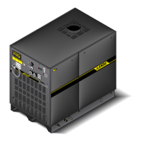
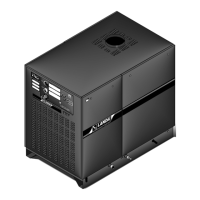
PRESSURE WASHER
10
Propane Gas:
The following pipe sizes should be used between the
regulator and the gas valve on the burner.
Distance From Regulator Pipe Size
0 - 50’ 1” 1 PS
50’ - 100’ 1-1/2” 1 PS
100’ - 200’ 1-3/4” 1 PS
Natural Gas:
The following pipe sizes should be used between the
meter and the cleaner.
Distance From Regulator Pipe Size
0 - 50’ 1-1/2” 1 PS
50’ - 100’ 2” 1 PS
100’ - 200’ 2-1/2” 1 PS
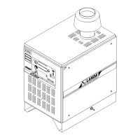
Venting:
Because this machine is installed indoors, regula-
tions or ventilation concerns may call for a chimney
or furnace pipe.
When venting the machine, if the machine is to be in
an enclosed area with a stack on it, be sure the flue
pipe is the same size as the stack on the machine. Poor
draft will cause the machine to soot and not operate
efficiently. When placing the machine for installation,
keep in mind that the machine should be positioned
in such a manner that the stack will be as straight as
Location of union and drip leg for connecting conversion
burner to house piping.
Control
Manifold
Figure 2: Union Location
3 in. (76.2 mm)
MINIMUM
Floor Level
Tee
Flow
Manual
Shut-off
Valve
1/8 in. N.P.T.
Plugged Pressure
Gauge Port
Union
Pipe Cap
possible and protrude through the roof of the building
at a proper location and at sufficient height to eliminate
down draft. The flue pipe of a gas fired machine shall
be installed with a down draft diverter.
Input - BTU Per Hour Draft Hood & Flue Pipe
Size
410,000 - 600,000 10 inch
600,000 - 750,000 12 inch
Draft Diverter:
The draft diverter (figure 3) should be installed at
least one (1) foot above the heating coil. The diverter
enhances the draft through the burner by severing
the chimney effect created in sections of furnace pipe
positioned below. It also helps prevent freezing of the
coil due to wind chill factors.
Figure 3
Optional
When the pressure washer is installed in a tightly
closed room without ventilation openings to the out-
doors or other rooms, provisions shall be made for
supplying air for combustion through special openings,
one near the floor line and the other near the ceiling,
each to be sized on the basis of one square inch or
more of free area for each 1,000 BTU input per hour.
See Figure 4.
When a room is of unusually tight construction and
has a ventilating fan, which may be used for exhaust-
ing air to outdoors - or has a vented fireplace - it is
recommended that combustion air be supplied to the
enclosed room through intakes extending to the outside
of the building and terminating in downturned fittings,
suitably arranged to prevent obstruction from snow
or rain, and including a protecting screen not smaller
than 1/4 inch mesh.
Figure 4
INSTALLATION
Ventilating Air Opening 1 sq. in. for each 1000 BTU per hour input.
Illustration showing air openings necessary to supply air for
combustion when heating appliance is installed in an enclosed room.
 Loading...