8.913-939.0 • LANDA VNG • Rev. 5/11
OPERATOR’S MANUAL
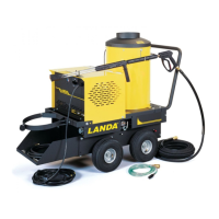
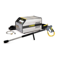
PRESSURE WASHER
8
INSTALLATION
Place machine in a convenient location providing ample
support, drainage and room for maintenance.
Location:
This machine is certified for indoor installation. Its
location should protect the machine from damag-
ing environmental conditions, such as wind, rain
and freezing.
1. The machine should be run on a level surface
where it is not readily influenced by outside sources
such as strong winds, freezing temperatures, rain,
etc. The machine should be located considering
accessibility of the components and the refilling
of detergents, adjustments and maintenance.
Normal precautions should be taken by operator of
machine to prevent excess moisture from reaching
power machine or electrical controls.
2. It is recommended that a partition be made be-
tween wash area and machine to prevent direct
spray from spray gun from coming in contact
with machine. Excess moisture reaching pres-
sure washer or electrical controls will reduce life
of machine and may cause electrical shorts.
3. During installation of machine, beware of poorly
ventilated locations or areas where exhaust fans
may cause an insufficient supply of oxygen. Suf-
ficient combustion can only be obtained when
a sufficient supply of oxygen is available for the
amount of fuel being burned. If it is necessary to
install a machine in a poorly ventilated area, out-
side fresh air may have to be piped to burner and
a fan installed to bring air into area.
4. Do not locate near any combustible material. Keep
all flammable material at least 20 feet away.
Allow enough space for servicing the machine.
Local code will require certain distances from floor
and walls. (Two feet away should be adequate.)
AVOID SMALL LOCATIONS OR AREAS NEAR
EXHAUST FANS.
Gas Codes:
Confer with local gas company and with proper mu-
nicipal officials regarding any specific code or regula-
tions governing the installation. The installation must
conform to local codes.
Electrical:
The machine, when installed, must be electrically
grounded in accordance with local codes. Check for
proper power supply using a volt meter; check the se-
rial plate for the correct requirements.
Gas Piping:
All piping must comply with local codes and ordinances
of the National Fuel Gas Code. A sediment trap or drip
leg must be installed in the supply line to the burner.
See figure 1.
A union shall be installed in the gas line adjacent to and
upstream from the control manifold and downstream
from the manual main shut-off valve.
A 1/8” N.P.T. plugged tapping accessible for test gauge
connection shall be installed immediately upstream of
the gas supply connection for the purpose of deter-
mining the gas supply pressure to the burner, and to
prevent damage to gas valve.
If a manual gas shut off valve is not in the gas supply
line within six feet of the machine and in an accessible
location, one shall be installed.
A manual shut-off valve shall be installed in the gas
supply line external to the appliance. See Figure 2.
The gas line should be a separate supply direct from
the meter to the burner. It is recommended that new
pipe be used and located so that a minimum amount
of work will be required in future servicing. The piping
should be installed to be durable, substantial and gas
tight. It should be clear and free from cutting burrs and
defects in structure of threading. Cast iron fittings or
aluminum tubing should not be used for the main gas
circuit. Joint compounds (pipe dope) should be used
sparingly on male threads only and be approved for
all gases.
Figure 1: Drip Leg
3 in. (76.2
mm)
MINIMUM
3 in. (76.2 mm)
MINIMUM
Sediment trap (drip leg) must be
installed in the supply line.
Drop
Gas
Valve
Gas
Valve
1/4” Test Port
(6”-14 WC or 1/2”
PSIG)
 Loading...