Do you have a question about the Laney CONCEPT CPC10 and is the answer not in the manual?
Guide to checking the product for damage upon arrival and retaining original packaging for future use.
Ensures proper grounding, advises against exposure to moisture, and specifies fuse replacement guidelines.
Provides input for connecting a CD or tape player.
Jack input sockets for all line level signals like keyboards or drum machines.
Controls input levels for CD/TAPE and Line, and adjusts high/low frequencies.
XLR input for low impedance microphones (200-600 Ohm).
Provides Line Out for monitors and External Speaker output for un-powered monitors.
Controls the main power supply for the unit.
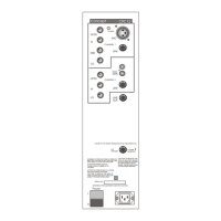
Adjusts overall output, frequency response (HI, MID, LO) for channels 1 and 2.
Details MIC, LINE, and CD/TAPE inputs for channel 1 and channel 2.
Provides Line Out and External Speaker output for connecting additional audio equipment.
Main switch to control the power supply to the unit.
Steps for connecting microphones and external equipment to the CPC products.
Recommended order for powering on auxiliary equipment, mixers, and speakers.
Illustrates how to connect various inputs and outputs for system setup.
| Channels | 10 |
|---|---|
| Inputs | 10 |
| Microphone Inputs | 4 |
| Line Inputs | 6 |
| EQ | 3-band |
| Auxiliary Sends | 1 |