1
1. HARDWARE OVERVIEW
3. HARDWARE INSTALLATION
The front console port allows a dumb terminal or PC with terminal emulaon soware to
locally access management funcons and connected devices.
The device ports allow simple and exible connecons to serial devices using adapters and
a standard CAT5 cable. Connect one end of the CAT5 cable to the device port and the other
end to an adapter that aaches to the serial console of the target system.
For example, to connect a PC to the console port of the EMG 8500, you need the RJ45 to
DB9F Adapter and a standard CAT5 cable which is supplied with the unit.
The default communicaon parameters for the device ports and console ports are:
• 9600 baud • 1 stop bit • 8 data bits • No ow control • No parity
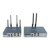
2. CONNECTING THE EMG 8500
Front View Back View
Reversed by Default
EMG
™
8500 Quick Start Guide
Edge Management
Gateway
1. CTS (In)
2. DSR (In)
3. RX (In)
4. GND
5. GND
6. TX (Out)
7. DTR (Out)
8. RTS (Out)
1. RTS (Out)
2. DTR (Out)
3. TX (Out)
4. GND
5. GND
6. RX (In)
7. DSR (In)
8. CTS (In)
Console Port (RS-232) Device Ports (RS-232)
!
Thank you for choosing Lantronix. Please register the EMG 8500 in order to receive nocaons for
rmware and documentaon updates at www.lantronix.com/product-registraon.
Default Pin Assignments
EMG 8500 Quick Start Guide
Accessories Part Number Quanty
External Universal AC (100W, 12V) Power Supply 520-0164-00 1
North American Power Cord - 110V AC power cord, 8
(2.43m), RoHS
500-041-R 1
RJ45 to DB9F Adapter 200.2070A 1
RJ45 to RJ45, CAT5 Cable, 6.6 (2 m) 200.0062 1
RJ45 Loopback Cable 500-153 1
Addional I/O and Connecvity FRUs are available
and sold separately.
varies varies
START
WHAT’S IN THE BOX
The EMG 8500 unit oers up to 8 RJ45 (RS-232) or USB serial device port connecons in two user-swappable, front I/O module device bays. The
aached equipment requires an available console, AUX, or serial port (RS-232). Dual Ethernet or dual SFP ports provide in-band management access,
allowing remote management of equipment using familiar tools such as Telnet or Secure Shell (SSH). Two user-swappable connecvity module bays
on the back of the EMG unit provide out-of-band management access via LTE cellular modem FRU, or a local terminal can be used. In the event that
the IP network is unavailable, the EMG 8500 unit can fail-over to the secondary connecvity interface. Once connected, the user has access to the
server or IT equipment’s command line interface (CLI) via the console port to perform maintenance or management tasks.
*DIO adapter is available and sold separately.
All EMG 8500 models are compable with a variety of equipment, including:
• Switches • Routers • Firewalls • Servers • UPS systems • PBX systems • Telecom switches • PDU (supported brands)
1. Install the unit on a desktop or other at, horizontal surface. You may oponally mount the EMG 8500 in a 19-inch rack or on a wall using the
oponal mount kit accessories. Warning: If rack mounng the EMG, do not block the air vents on the sides of the unit. If mounted in an enclosed
rack, it is recommended that the rack have a venlaon fan.
2. Connect the equipment to the numbered device ports on the front of the unit using the appropriate cables and adapters.
3. Connect the unit to the network using the upper network port (Ethernet 1).
4. Connect the power cord to apply power. The top front LED turns green to indicate that power is ON and at least one of the Ethernet ports has a link
or both Ethernet ports are disabled. The LED blinks red if none of the enabled Ethernet ports has a link.
5. Wait about a minute and a half for the boot process to complete. The rst me you power up the EMG unit,
Eth1 tries to obtain its IP Address via DHCP. View this IP Address by running Lantronix Provisioning Manager
applicaon or by connecng a terminal to the console port to access the command line interface.
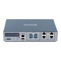
Soware Reversible
DIO*
LEDs
Device Ports (Modular)
Bay 1
Bay 2
Console Port
Micro SD
USB Port
Connecvity Ports (Modular)
Bay 1
Bay 2
Ethernet
SFP
Power input
EMG851210SP with USB and RJ45 FRUs shown.
Addional FRU combinaons are available.
Not Reversible