Do you have a question about the Lars Thrane iridium LT-3100S and is the answer not in the manual?
Recommendation for professional installation by trained and authorized personnel.
Instruction to turn off the main power switch before installation or servicing.
Specifies the acceptable input voltage range for the equipment.
Requirement for power supply protection using fuses or circuit breakers.
Mandatory use of DC circuit breaker as ON/OFF switch.
Information on overcurrent protective devices and Lars Thrane A/S responsibility.
Prohibition of operation in environments with flammable gases or fumes.
Recommended distances from compasses to avoid interference.
Warning against disassembling or modifying the equipment.
Instruction to avoid contact with live circuits and disconnect before touching.
Procedure for immediate power off in case of smoke or water leaks.
Designation of the DC mains connector as a disconnection device.
Requirement to maintain safety distance from the antenna unit.
Definition of 'Warning' as a procedure that may cause hazard.
Definition of 'Important' for essential information and potential equipment damage.
Definition of 'Note' providing essential information to the reader.
Identifies installers and service personnel as primary readers.
Overview of the LT-3100S GMDSS Satellite Communications System.
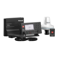
List of components included in the LT-3100S GMDSS Satellite Communications System.
Checking shipping cartons and system for damage or defects upon receipt.
Warning about applying power if shipping damage is present.
Optional GMDSS parts not included in the basic system.
Optional SSAS parts not included in the basic system.
Optional mounting accessories for the system units.
Optional cables and connectors required for system setup.
Illustration of LT-3100S GMDSS system components and interfaces.
List of primary and optional units provided by Lars Thrane A/S.
Description of the external interfaces on the LT-3110S Control Unit.
Guidelines for optimal installation location and environmental conditions.
Illustrations of bracket and flush mount options for the control unit.
Details on connecting the LT-3120 Handset to the control unit.
Key characteristics of the LT-3120 Handset.
Note on handset operation with the LT-3121 Cradle for off-hook detection.
Information on mounting the LT-3121 Cradle and its magnetic properties.
General guidelines for mounting the LT-3130 Antenna Unit.
Guidelines for positioning and mounting the antenna unit for optimal performance.
Note on the required HVIN version for the LT-3130 Antenna Unit.
Procedure and torque specifications for connecting the coaxial cable to the antenna unit.
Safety distance requirements for the antenna unit to comply with regulations.
Requirements for separating the antenna unit from radar and radio antennas.
Information on indoor mounting and connecting the LT-3140S Interface Unit.
Details on connecting and mounting the LT-3150S Alarm Panel.
Information on flush mounting the LT-3150S Alarm Panel with its bracket.
Details on connecting the LT-3160S Printer Adapter to a GMDSS printer.
Procedure for installing the bracket mount for the antenna unit.
Illustrations and specifications for the bracket mount for the antenna unit.
Procedure for installing the pole mount for the antenna unit.
Illustrations and specifications for the pole mount for the antenna unit.
Details on the DC power input for the LT-3110S Control Unit.
Location of the chassis ground connector on the Control Unit.
Procedure for inserting, replacing, or removing the GMDSS SIM card.
Information on the Iridium GMDSS SIM card and activation process.
Description of the Ethernet LAN (RJ-45) interface on the Control Unit.
Details on the 10-pin auxiliary connector and its supported interfaces.
Minimum requirements for the coaxial cable connecting the Control Unit and Antenna Unit.
Calculations and examples for maximum coaxial cable length based on resistance.
Available interfaces on the LT-3140S Interface Unit and external equipment connections.
Details on DC input voltage and chassis ground for the Interface Unit.
Overview of the control unit's display layout and physical buttons.
Functionality of the Power and DIM button for system control and display settings.
Procedure for activating a Distress Alert using the DISTRESS button.
Functions of the Off-hook and On-hook buttons for call management.
Usage of MENU, Navigation, and Soft Key buttons for system interaction.
Overview of the display layout, including status bar and view area.
Explanation of icons and status indicators in the control unit's status bar.
Icons representing network connection status on the LT-3110S Control Unit.
Icons indicating Iridium service status, such as call types.
Icons for system notifications like missed calls and messages.
Icons for audio status (mute) and numeric keypad input modes.
Icons for Bluetooth connection and Tracking service status.
Icons indicating Bridge Alert Management (BAM) status and priority.
How to access and navigate the main menu and its sub-menus.
Detailed list of sub-menus and entries within the LT-3110S Control Unit menu.
Overview of system registration status with Iridium Network.
Explanation of system texts and their corresponding operational status.
Procedure for activating a Distress Alert from the Control Unit or Alarm Panel.
Receiving and configuring Maritime Safety Information (MSI) messages.
Procedures for placing priority voice calls and sending priority messages.
Establishing non-priority voice calls using on-hook or off-hook modes.
Step-by-step guide for making voice calls in on-hook mode.
Step-by-step guide for making voice calls in off-hook mode.
Description of states during voice call connection and successful connection.
Sending and receiving non-priority messages.
Using the built-in GNSS receiver for vessel position determination.
Overview of the Bridge Alert Management concept and system implementation.
Checking BAM status and navigating the alert list for conditions.
Definitions of alert priorities and states.
Table defining BAM alert icons, their priority, and state.
Procedures for acknowledging alerts and combining similar alerts.
Concepts of responsibility transfer and revaluation for alerts.
Time synchronization via GNSS and configuring printer output.
Instructions for accessing the LT-3110S Control Unit's web server.
Overview of the web server dashboard and configuration web pages.
Procedure for updating the system software using the web server.
How to download a diagnostic report for troubleshooting.
Step-by-step guide to access the web server, including handling security warnings.
End-user responsibilities for service and repair of the GMDSS system.
Procedure for contacting the distributor or dealer for support and troubleshooting.
List of alert generating functions within the BAM concept.
Categories for BAM alerts indicating acknowledgement and responsibility transfer.
Details of Caution priority alerts, including ID, title, and conditions.
Details of Warning and Caution priority alerts.
Details on alerts related to missing or unknown SIM cards.
Certification, standards, and general system specifications.
Power, weight, dimensions, IP rating, and interfaces of the control unit.
Specifications for the LT-3120 Handset, including weight and dimensions.
Specifications for the LT-3121 Cradle, including weight and dimensions.
Specifications for the LT-3140S Interface Unit, including power, IP rating, and interfaces.
Specifications for the LT-3150S Alarm Panel, including weight, IP rating, and interfaces.
Specifications for the LT-3160S Printer Adapter, including weight, IP rating, and interfaces.
Dimensional drawing of the LT-3110S Control Unit.
Dimensional drawing of the bracket mount for the control unit.
Dimensional drawing of the flush mount for the control unit.
Dimensional drawing of the LT-3130 Antenna Unit.
Dimensional drawing of the LT-3140S Interface Unit.
Dimensional drawing of the LT-3150S Alarm Panel.
Dimensional drawing of the LT-3160S Printer Adapter.
Dimensional drawing of the pole mount for the antenna unit.
Dimensional drawing of the bracket mount for the antenna unit.
Dimensional drawing of the LT-3120 Handset.
Dimensional drawing of the LT-3121 Cradle.
EU Declaration of Conformity status.
| Brand | Lars Thrane |
|---|---|
| Model | iridium LT-3100S |
| Category | Marine Radar |
| Language | English |