3
-
5
5
Control Termination:
Legend
Control
circuit
equipment
Ref. No.
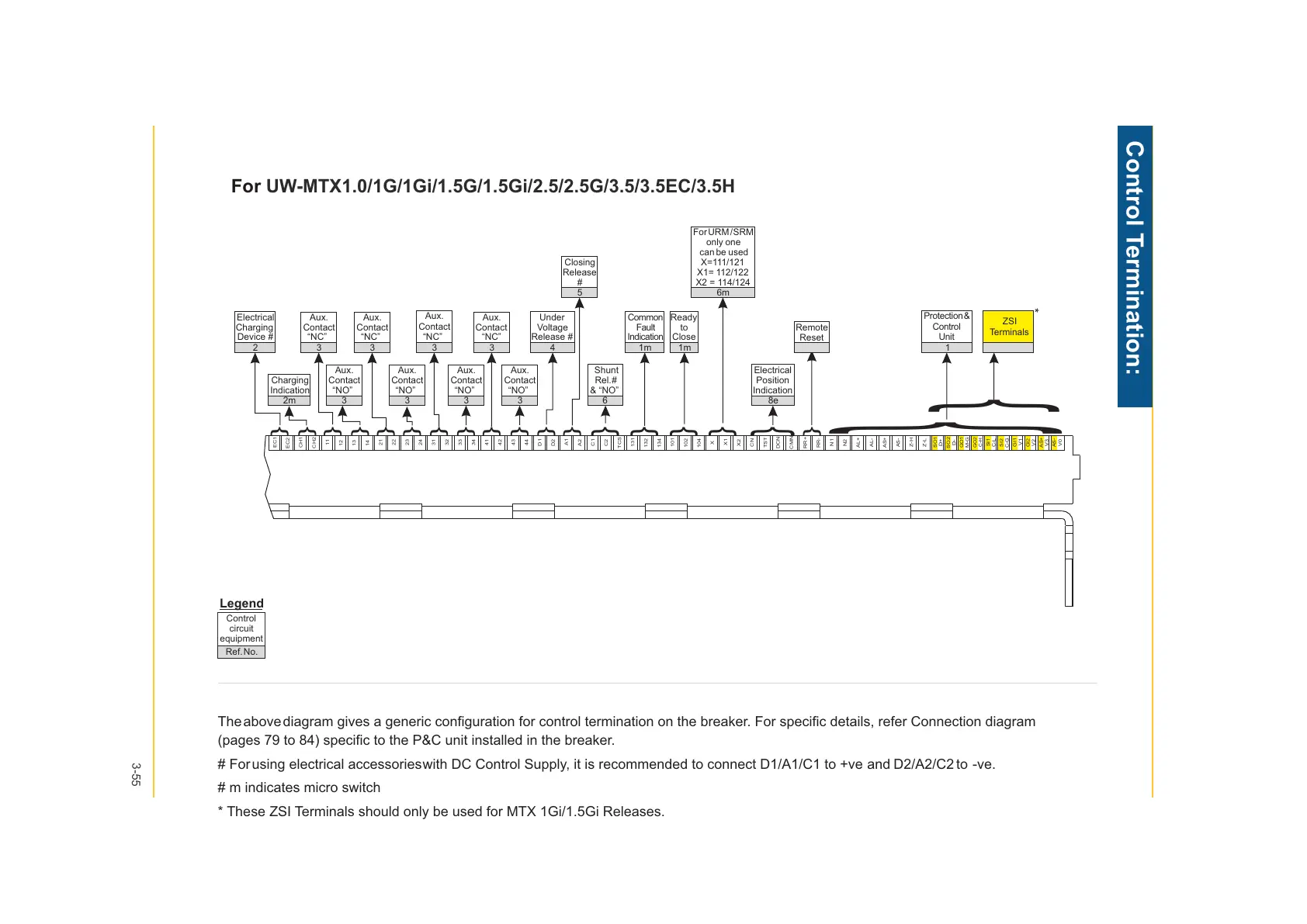
The above diagram gives a generic configuration for control termination on the breaker. For specific details, refer Connection diagram
(pages 79 to 84) specific to the P&C unit installed in the breaker.
# For using electrical accessories with DC Control Supply, it is recommended to connect D1/A1/C1 to +ve and D2/A2/C2 to -ve.
# m indicates micro switch
* These ZSI Terminals should only be used for MTX 1Gi/1.5Gi Releases.
EC1
EC2
CH1
CH2
11
12
13
14
21
22
23
24
32
33
34
41
42
43
44
D1
D2
A1
A2
C1
C2
TCS
131
132
134
101
102
104
X
X1
X2
CN
TST
DCN
CMN
N1
N2
Z-L
Z-H
AL+
AL-
RR+
AS+
AS-
RR-
31
}
}
Electrical
Charging
Device #
2
Aux.
Contact
“NC”
3
Aux.
Contact
“NC”
3
Aux.
Contact
“NC”
3
Under
Voltage
Release #
4
Closing
Release
#
5
Common
Fault
Indication
1m
Ready
to
Close
1m
only one
can be used
X=111/121
X1= 112/122
X2 = 114/124
6m
Electrical
Position
Indication
8e
Remote
Reset
Protection &
Control
Unit
1
Shunt
Rel. #
& “NO”
6
Aux.
Contact
“NO”
3
Aux.
Contact
“NO”
3
Aux.
Contact
“NO”
3
Charging
Indication
2m
Aux.
Contact
“NC”
3
Aux.
Contact
“NO”
3
}
ZSI
Terminals
SO1
D+
SI1
C-L
GO2
C-H
SI2
C-G
GI1
V1
AS+
V3
AS-
V0
SO2
D-
GI2
V2
GO1
M-G
*
}
}
}
}
}
}
}
}
}
}
}
}
}
}
}
}
}
ForURM / SRM
For UW-MTX1.0/1G/1Gi/1.5G/1.5Gi/2.5/2.5G/3.5/3.5EC/3.5H
 Loading...