50 INSTALLATION AND MAINTENANCE MANUAL 554515_A_PUB_DATE_1_FEB_2014.DOC
ELECTRONIC CONTROLLER WITH BLUE PCB AND GRAPHICAL DISPLAY
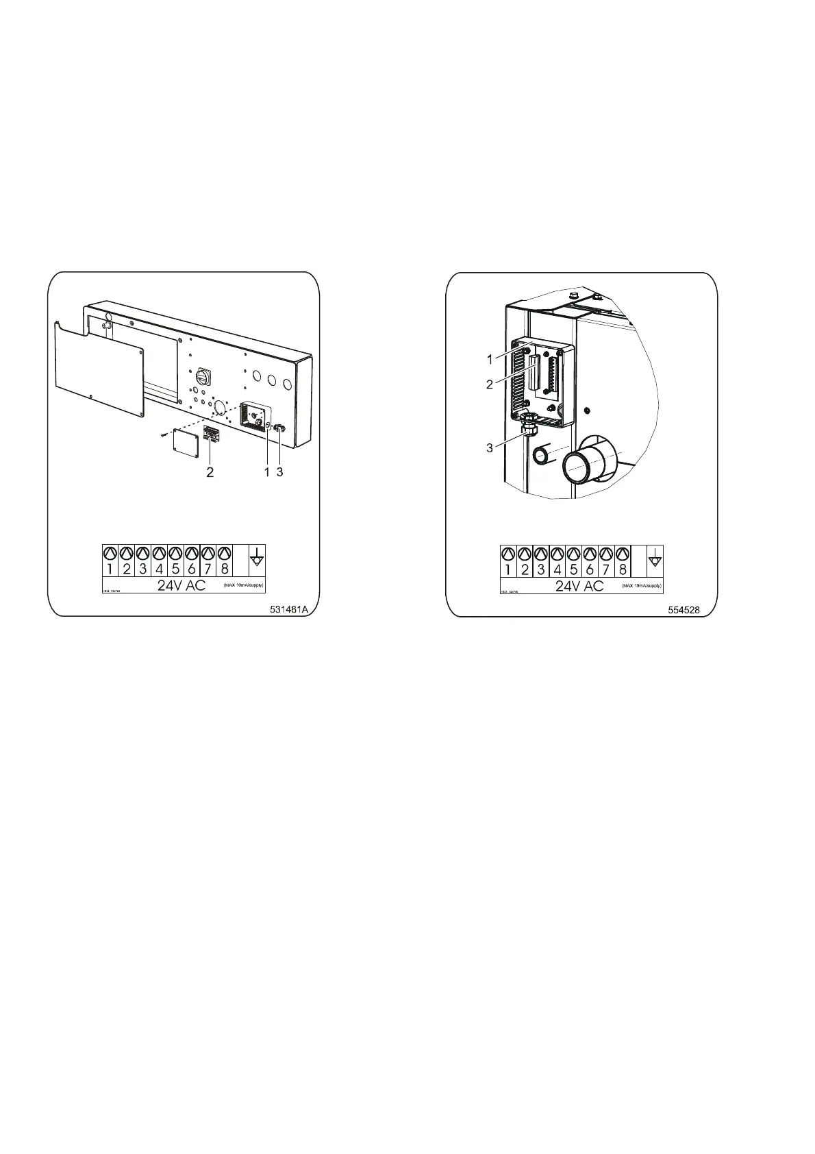
For electric connection of supply control signals a plastic box is available on the back side of the machine
(see figure 4.4.H., pos.1) with the terminal box with LED signalization of activation of the respective pump, (pos.2).
Under the terminal box there is a label for electric connection. Detail connection of signals could be also
found on the electric scheme of the machine. Signals for supply pumps control are 24V AC. Maximum current
for control circuits of pumps must be limited to 10mA. Lead the cable for connection of pumps control signals
through the plastic cable bushing, position 3. After connection of conductors to the respective positions of the
connector „P“ (screw clamps), fix up the cable by tightening the cable bushing) against disconnection and
close the box with the cover. For details about liquid soap supply system programming, see Programming
manual.
Electrical connection label
Figure 4.4.I – Machines 80-100-120 / 180-230-275 lb
Electrical connection label
Figure 4.4.H – Machines 33-40-55 kg / 80-100-125 lb
 Loading...