Do you have a question about the LBA GROUP LA BARRIERE AUTOMATIQUE 4 and is the answer not in the manual?
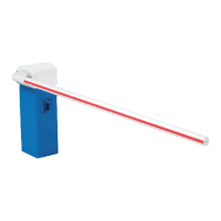
| Barrier Length | Up to 4 meters |
|---|---|
| Power Supply | 230V AC |
| Brand | LBA GROUP |
| Barrier Type | Automatic |
| Control | Remote control, push button |
| Material | Steel |
| Safety Features | Obstacle detection |
Introduction to the operating instructions and company's commitment to customer satisfaction.
Details on user safety liability and comments on barrier installation and pedestrian traffic.
Conditions under which the manufacturer is not liable for damages to people or objects.
Protection of manual content and prohibition of unauthorized reproduction or communication.
Manufacturer's liability for defects under normal use and no unauthorized intervention.
Contact details for technical issues before, during, and after sale.
List of European standards with which the barriers comply.
Importance of complying with directives for correct disposal and avoiding environmental damage.
Defines intended use for regulating vehicle entry/exit and detection requirements for vehicles.
Lists prohibited uses like regulating pedestrians or animals and potential hazardous situations.
Outlines user's legal safety obligations, training, and maintenance responsibilities.
Warns against modifications and advises contacting the manufacturer before any changes.
Defines staff considered qualified for barrier operation and maintenance.
Identifies the barrier area as hazardous due to potential crushing/cutting risks when powered.
Provides dimensions and direction diagrams for different barrier models.
Specific dimensions and boom length for the LBA 4 model.
Specific dimensions and boom lengths for LBA 6, 6R, and 63PK models.
Specific dimensions and boom lengths for LBA 7, 7R, and 74 models.
Table detailing key features, sheet metal, boom, motor, and control for various models.
Specifies voltage, frequency, and consumption requirements for the barrier.
Lists immunity standards and environmental conditions the barrier can withstand.
Details MTBF, MCBF, number of operations, MTTR, and IP ratings for different barrier models.
Safety guidelines for loading, transporting, and unloading barrier components.
Procedures for checking delivery for damage or missing parts and filing complaints.
Recommended conditions for storing barrier elements, including temperature and humidity.
Recommendations for constructing concrete foundations and conduit dimensions.
Details on constructing foundations and securing anchor rods for non-rotary base plates.
Details on constructing foundations and securing anchor rods for rotary base plates.
Step-by-step guide for installing the barrier housing onto the base plate.
Specific installation steps for mounting the housing on a non-rotary base plate.
Specific installation steps for mounting the housing on a rotary base plate.
Procedures for assembling the boom onto the barrier mechanism.
Steps for assembling the boom on the LBA4 model.
Steps for assembling the boom on LBA6, 6R, and 63 models.
Steps for assembling the boom on LBA7, 7R, and 74 models.
Notes factory settings and the possibility of on-site adjustments for optimal operation.
Instructions on how to power on the barrier after electrical connection.
Detailed steps for adjusting barrier opening and closing positions using sensors.
Specific sensor adjustment procedures for irreversible barrier models.
Specific sensor adjustment procedures for reversible barrier models.
How to adjust the counterbalance spring for boom weight compensation and auto-lifting.
Overview of the user interface components: screen, buttons, and LEDs.
Overview of the barrier's input and output terminals and functions.
Detailed description of all available inputs and outputs with their terminal assignments.
Default configurations for inputs and outputs, noting potential customer variations.
Explanation of local control keys (ESC, ENTER) and their functions for navigation and commands.
How to view barrier status using the screen and indicator LEDs.
Overview of various screen displays showing advanced settings, cycles, and status.
Function of LEDs for indicating input/output status and available voltages.
List of status messages displayed on the screen and their meanings.
List of messages related to safety component activation and error codes.
Selection between "OP" and "ADMIN" user profiles, with ADMIN requiring a password.
Accessing advanced information about the barrier's program and control board contents.
Functions for stopping and restarting the PLC without powering down the barrier.
Accessing and modifying user-configurable settings for barrier adjustment.
Procedure for configuring the barrier's IP address via DHCP or static assignment.
How to modify the barrier program using an SD card.
How to record the barrier program onto an SD card.
Accessing statuses of local variables for troubleshooting purposes.
Configuration of the control board as a slave for RS485 Modbus communication.
Configuration of the control board as a server for Ethernet TCP/IP Modbus communication.
Steps to modify the barrier's IP address via the control board menu.
Modbus exchange table detailing data types, addresses, and descriptions for board communication.
How to connect the barrier to a network and access it via a web browser.
Explanation of authentication levels (None, OP, Admin) for web server access.
Describes the web server's home page view and control possibilities for different profiles.
Access to additional configuration and information tabs within the web server.
Configuring the barrier's network settings, including static or DHCP IP addresses.
Accessing and modifying user parameters for barrier settings.
Accessing statuses of local variables for troubleshooting via the web interface.
Accessing advanced information about the barrier's program and control board.
Guidelines on cleaning frequency, methods, and precautions to avoid damage.
Schedule for periodic maintenance tasks, including checks and inspections.
Procedure for manually opening the barrier during a power outage for specific models.
Procedure for manual opening during power outages for other models.
Table of common failures, possible causes, and troubleshooting steps.
List of common error messages from the variable speed drive and recommended actions.
Reference to the assembly section for boom replacement procedures.
Procedures for replacing the geared motor unit on different barrier models.
Step-by-step guide for replacing the geared motor unit on the LBA4 model.
Step-by-step guide for replacing the geared motor unit on LBA 6/6R/63PK models.
Step-by-step guide for replacing the geared motor unit on LBA 7/7R/74 models.
Procedures for replacing the boom stops on specific barrier models.
Procedure for replacing stops on LBA 6/6R/63PK models.
Procedure for replacing stops on LBA 7/7R/74 models.
Step-by-step guide for replacing the barrier's position sensors.
Procedure for replacing the counterbalance spring, chain, or quick link.
Procedures for reversing the operating direction of different barrier models.
Steps to reverse the operating direction of the LBA4 barrier.
Steps to reverse the operating direction of LBA 6/6R/63PK barriers.
Steps to reverse the operating direction of LBA 7/7R/74 barriers.