■
Measures to Take When Proximity Switch/photoelectric Switch, etc. Malfunction
Take possible measures among the following in the order of 1 to
12. Each measure will improve noise reduction.
■ Corrective measures
1. Use twisted pair/shielded wire as a sensor signal line, and connect the
shielded wire to common.
2. Separate the inverter and power line from the sensor circuit as much
as possible.
(More than 10 cm desirable)
3. Remove the grounding wire when the power supply for the sensor is
grounded.
4. Lower the carrier frequency as much as possible. Up to approx. 10
kHz when low-noise operation is necessary.
5. Install a zero-phase reactor on the output side of the inverter. (Type:
RC5078, RC9129)
6. Install an LC filter on the input side of the inverter. (Type: FS)
7. Install a capacitive filter on the input side of the inverter.
(Type: 3XYHB-105104)
8. Use a metal conduit or shielded cable for power supply wiring.
9. Use 4-wire cable as a motor power line, and ground one of the wires.
10.Install a drive isolation or noise reduction transformer for the inverter
power supply.
11.Gorund the power supply for the sensor via a 0.01-0.1
o(630V 0.1µF)
12.Separate the inverter power supply from the sensor power supply
system.
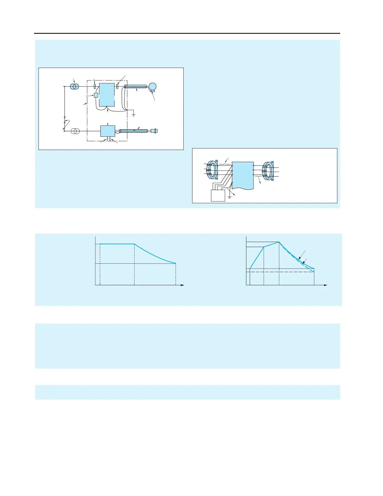
■ Connection
of ty reactors and u capacitive filter
■ Continuous Operation Torque Characteristics
■ Motor Temperature Rise
When a general-purpose motor is used in variable-speed operation with an inverter, the temperature rise of the motor will be slightly greater than in cases
where commercial power is used. The causes are shown below:
Influence of output waveform
Unlike commercial power, the output waveform of an inverter is not a perfect sine wave, and contains higher harmonics.
Therefore, the motor loss increases and the temperature is slightly higher.
Reduction in the motor cooling effect
Motors are cooled by the fan on the motor itself. When the motor speed is reduced by an inverter, the cooling effect will
decrease.
Therefore, lower the load torque or use an inverter motor to control temperature rise when the frequency is below the frequency of commercial power.
Ground this part via a 0.01-0.1 µF
capacitor instead of direct grounding
11.
Drive isolation or noise
reduction transformer
10.
Zero-phase reactor
3-times winding (4 T)
or more
6.
Zero-phase reactor
3-times winding (4 T)
or more
5.
Lower the carrier
frequency as much
as possible
4.
Metal conduit
orshielded
cablegrounded
atone point
8.
Use 4-wire cable a
a motor power line
and ground one of
the wires.
9.
Use twisted bare/shielded wire.
Connect the shielded wire to the
common signal.
1.
3. Avoid direct grounding
Power
supply
R
S
T
U
V
W
E
Inverter
IM
Sensor
DC power
supply
for sensor
FC
+
-
Step-down transformer
Control
power supply
Capacitive
filter
7.
Separate
the power
system
12.
Control panel
or machine
frame
Separate the inverter and power
line from the sensor circuit
as much as possilbe.
(More than 10 cm)
2.

 Loading...