5
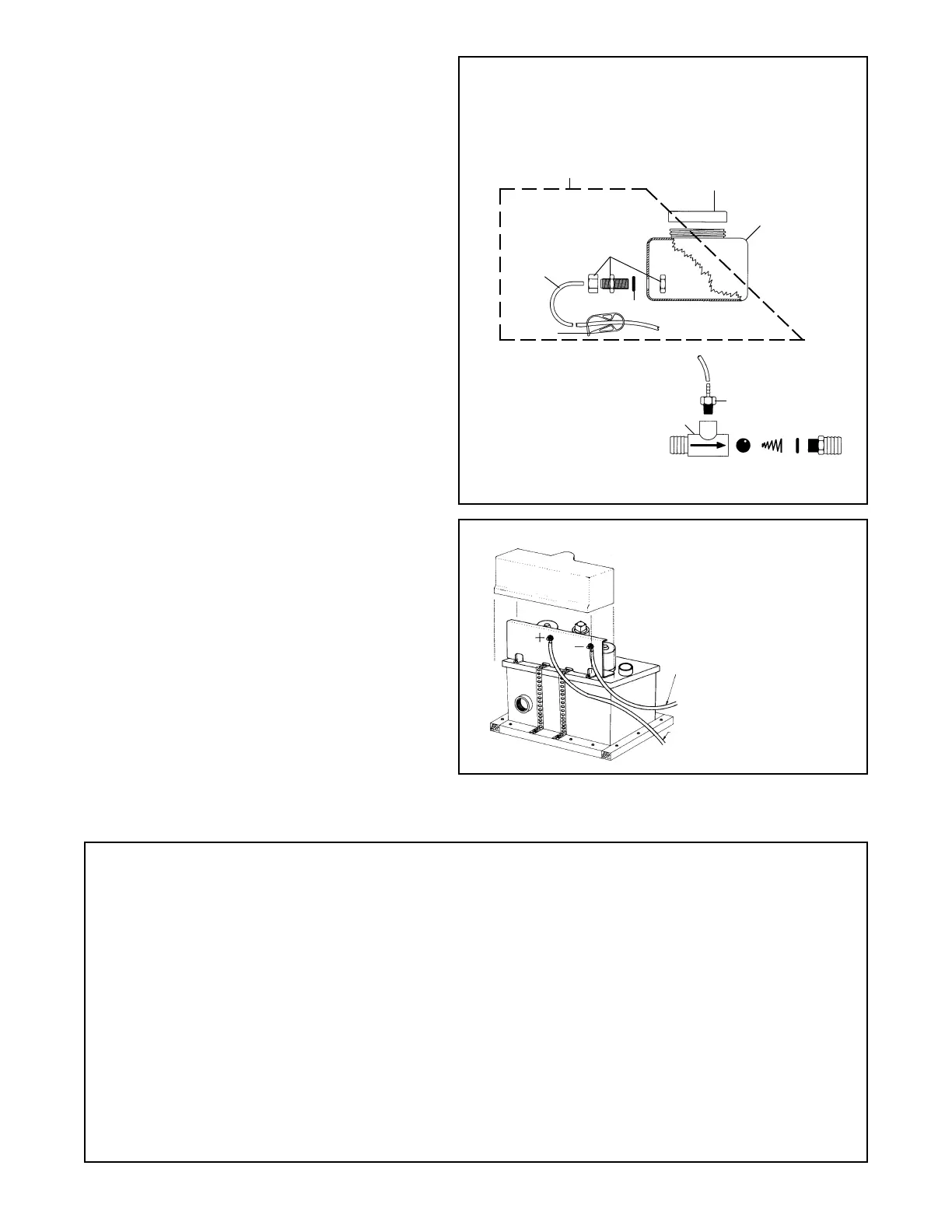
Fig. #8
To Battery Negative
To Protected Battery Positive
(fuse or circuit breaker)
1203B1
31-304C
31-304A
(ASSY)
31-302
31-304W
31-305
31-301
➀
T-CHECK VALVE EXPLODED VIEW
AND PARTS LIST:
1 Valve Body 31-307D
2 Siphon check valve 31-308W
3 Ball CH12
4 Spring CH8
5 O - Ring 31-307E
6 Discharge Adapter 31-307D1
Salt Feed Tank complete - 31-3001
T-Check Valve complete - 31-307W
SALT FEED TANK EXPLODED VIEW AND PARTS LIST:
Fig. #7A
Lectra/San EC SPECIFICATION TABLE
ELECTRICAL:
Voltage Nominal 12VDC 24VDC 32VDC
Voltage Minimal 11.5V 22.0V 31.0V
Power 1.7 amp hr 1.5 amp hr. 1.5 amp hr.
Current 50 A 42 A 35 A
Fuse/Breaker 60 A 50 A 50 A
Length of circuit: Wire Gauge
0-15' #6 AWG #8AWG #10AWG
15'-25' #4 AWG #6AWG #6AWG
26'-50' #1 AWG #4AWG #6AWG
☞☞
☞☞
☞NOTES: 1. Wire distance is determined by measuring from
the battery to the Lectra/San and back again.
2. Minimal Voltage is read across the electrode
pack while the system is operating in the treat-
ment (2nd) cycle.
3. Requires ocean grade salinity for proper con-
ductivity.
Max Amperage: 12VDC 24VDC 32VDC
Mixer Motor amp 5 4 4
“A” Fuse Type MDL 6 1/4 6 1/4 5
Electrode Pack 25 22 22
“B” Fuse Type MDL 35 30 30
Solid Reduction Motor 20 16 9
“C” Fuse Type MDL 30 25 20
Gallons of Waste Treatable/Day: 576
Maximum Roll/Pitch Angle: 30°
Maximum Temperature Exposure: 120° F
Maximum Total Flush Volume: 1.5 Gallons/Flush
☞ Atlantes owners: Use deodorant tank for salt
mixture, reduce concentrate ratio by 1/2.
ELECTRIC WIRING
WARNING: Danger of electric shock. Be
sure to disconnect power.
1. Run supply wire to Positive and Negative
terminals using specification table for wire
size and circuit breaker.
2. Connect wires to Positive and Negative ter-
minals on Treatment Tank (Fig. #8).
3. Connect ribbon cable, (#31-404) from Con-
trol Indicator Panel to the Control Module
(Fig. #10). Secure strain relief.
4. If you wish to flush an electric toilet (other
than the Atlantes) by pushing the Lectra/San
EC Control Indicator Panel, a Raritan Con-
tinuous Duty Solenoid must be installed and
wired per Fig. #9. (Atlantes see Fig. #9A.)
Failure to follow this correctly will result
in damage to the Lectra/San EC control
board and will void warranty.
IMPORTANT: Check polarity before turn-
ing on power.
5. Follow start up procedure under Recommis-
sioning and Start up.
WARNING: All control boards are pretested
at the factory. Burnt control board compo-
nents or foils are a result of improper wiring
by the installer. Board replacement in these
cases are not covered by Raritan's limited
warranty.
➂ ➃ ➄ ➅
➁
1203B1 O-Ring
31-301 Salt Feed Tank
31-302 Salt Feed Tank Cap
31-304A Adapter Assembly
31-304C Metering Thumbwheel
31-305 1/4" Tubing
 Loading...