5
Display Keypad Installation & Wiring JLC-11
(For dual actuator tabs, connect actuators from same tab in parallel)
Mounting Display Keypad:
1. Locate the display keypad at the helm where it is convenient to access and view the
LED indicators and a flat level surface.
2. Drill one 2.625” (67mm) hole as shown on page 6 for mounting display. Remove the
aluminum mounting plate from four mounting studs. The aluminum mounting plate
can be used as a drill template.
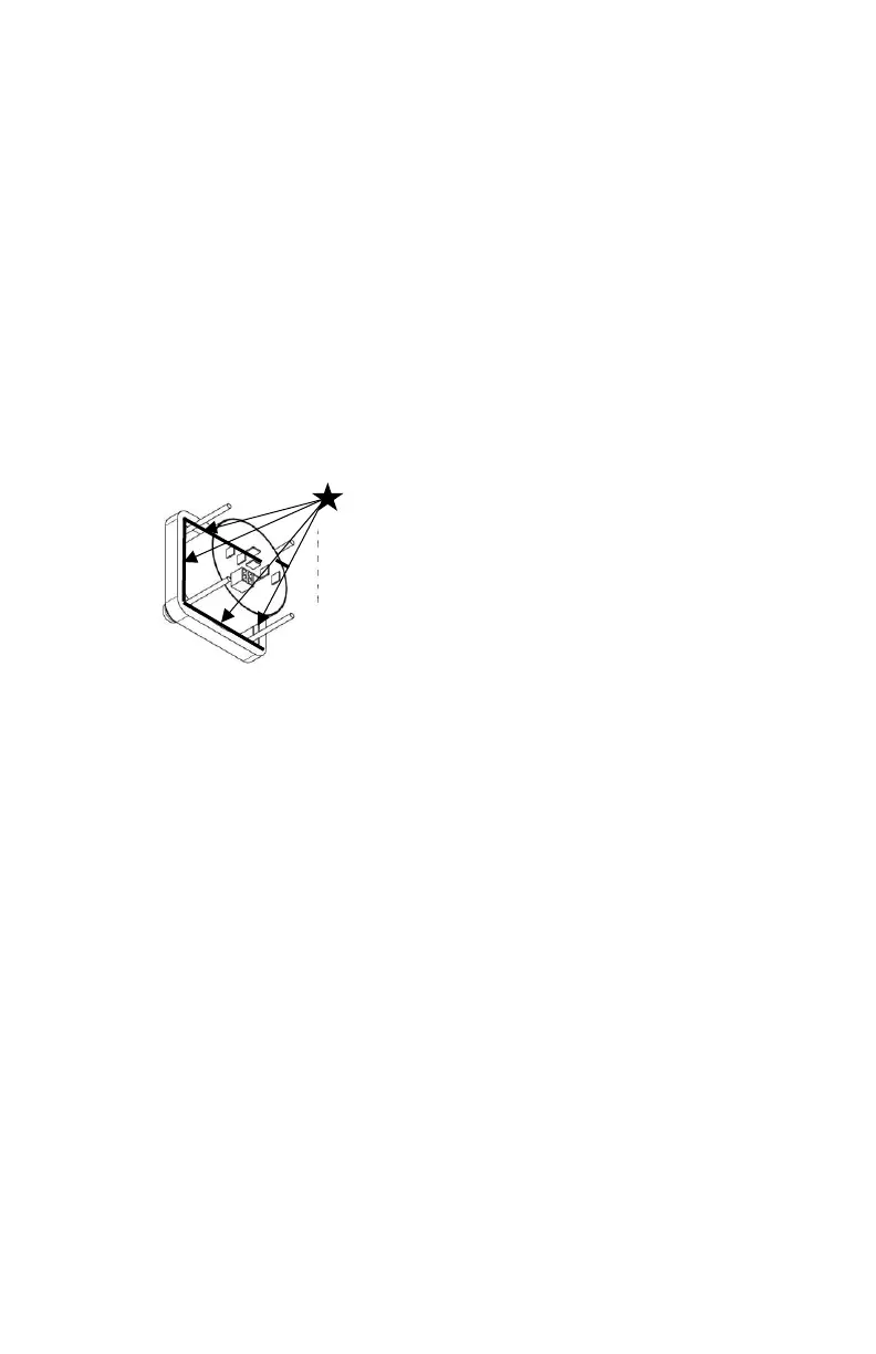
3. Apply a bead of silicone sealant around the underside of the display where the
rubber overlay meets the black potting material. This will prevent water from
entering under the display and reaching the wiring connections. See the diagram
below.
4. Mount the display with the aluminum plate, washers and nylon nuts provided. Only
use nylon nuts provided. Do not overtighten the nylon nuts.
Display Keypad Wiring:
1. Refer to wiring diagrams for the JLC-11 wiring connections.
2. The red (+12vdc or +24vdc) wire from the boat’s fuse panel and black battery
negative wires should be a minimum size of 14 AWG (2.5mm²).
3. Important: DC voltage source connected to JLC-11 keypad must match actuator
voltage (first letter in actuator serial A, C or S =12vdc, B or D = 24vdc).
4. The AUX terminal must be connected to ignition key run position or accessory
switch to automatically retract the tabs when key is switched to OFF and turn on
the display when key is switched to ON.
5. For dual station connections, a second JLC-11 keypad and one JR-** (**=length in
feet) serial communication cable/plug assembly is required. See wiring diagram on
page 7 for JR plug connection point.
6. For single station NMEA 2000 connection see wiring diagram. One JLC-NMEA
adapter is required to connect to the JLC-11. A NMEA 2000 cable drop and any
NMEA backbone tees must be purchased separately. For dual station NMEA 2000
systems, two JLC-11 and two JLC-NMEA adapters are required.
7. For dual actuator per tab installations, connect both actuator wires from each tab
in parallel and follow the wiring diagram on page 8. Connect each actuator white
wire to white wire and black wire to black wire from the same tab to the back of the
keypad or terminal strip if using a W4-** cable.
 Loading...