• CC represents a contact closure sensor channel. There are ve CC channels: CC1 through CC5•
• PDC represents a dry contact signal actuator channel that is powered. There are two PDC channels:•
PDC1 and PDC2. Note that each PDC channel has two electrical polarity markings below it: -
(negave) and + (posive), which you must follow when connecng an EMKA door handle
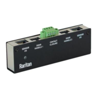
▶ DX2‑PD2C5 terminals, DIP switches, and LEDs:
Terminals, DIP switches, and LEDs are separated into two rows as shown below
Numbers Components
CC and PDC channels.
• Top row:•
Four CC channels (CC2 - CC5).
Two PDC channels (PDC1 - PDC2).
• Boom row:•
One CC channel (CC1).
See
Connecng Detectors/Switches to DX2-CC2 (on page 22) for how to
connect CC sensors or DC switches.
Dip switches for conguring the Normal state of each CC channel. See
Adjusng DIP Switches (on page 53).
• Top row:•
Dip switch 1 controls CC2.
Dip switch 2 controls CC3.
Dip switch 3 controls CC4.
Dip switch 4 controls CC5.
32
 Loading...