17
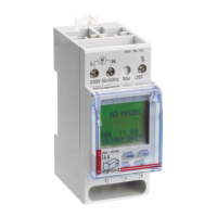
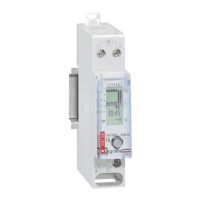
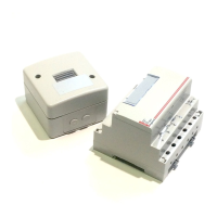
Light sensitive switch and photocell assembly
Connection
DIAGRAM A
Programme 1
Normal operation :
- link terminals B-C.
The lamp is on at nightfall and
off at daybreak.
Programme 2
Reverse operation :
- link terminals B-C
- link terminals E-F
The load is powerel during
daylight, and is switched off
after dark.
DIAGRAM B
Programme 3
Automatic operation to on with
manuel off :
Set the selection switch to
- following automatic switch on, a
manual switch off is possible by
pressing the (EM) button.
The unit will function automatically
at the next nightfall.
The button AM (if installed) : permits
manual on.
DIAGRAM C
Programme 4
Automatic operation to off with
manuel on :
Set the selector switch to
- following on automatic switch off a
manuel switch on is possible by
pressing the button (AM).
Automatic extinction is carried-out
as soon as daylight is sufficient.
- the button EM (if installed) permits
manuel off.
18
Light sensitive switch and photocell assembly (continued)
Setting
Connection (continued)
Attention : fail to observe the wiring information may result in domage to the product. It is important not to connect
the mains supply to the terminals A, B, C, D, E, F.
Modular light sensitive switch (pre-set to 20 lux)
Set light level with the potentiometer.
 Loading...