E-Flex Relay Panel (EFRP) Installation Guide
Please Read before Installing
F586 Rev. 2 Lehigh Electric Products Co. 6265 Hamilton Blvd.., Allentown, Pa. 18106 Tel: 610-395-3386 Website: www.lehighdim.com
Scan for EFRP configuration programming videos.
Step 7: Timeclock/Demand response, Emergency Contact closure Inputs
RISK OF DEATH OR ELECTRIC SHOCK! Before wiring or servicing the unit, make sure
upstream source of power is off via a circuit breaker.
If the high voltage shield is removed, the panel must be accessed by a certified technician following local
codes.
Wiring for both inputs is NEC Class 2/PELV. Follow all national and local electrical codes. The inputs must be
used with a dry contact closure device.
#24-12 AWG wires, strip length – ¼ in., torque – 3.5 lbs
If the Emergency input is open, the E-Flex panel will enter Emergency mode. All outputs that are assigned to
this input will turn on, 0-10V outputs will be driven to 100% and local control from sensors or other inputs
will be disabled.
Emergency Enable/Disable (EMERG-J12)
Jumper J12 (EMERG) is used to enable or disable the emergency input. To enable, position the jumper across
J12 pins 1-2. To disable (default) position the jumper across J12 pins 2-3.
DMX Port Wiring
E-Flex provides a DMX512 (ANSI E1.11-2008) input and thru ports with RDM (ANSI E1.20-2010) support.
Recommend Liberty 24-2P-P485-WHT, Belden 9841 or 9842.
RISK OF DEATH OR ELECTRIC SHOCK! Before wiring or servicing the unit, make sure
upstream source of power is off via a circuit breaker.
If the high voltage shield is removed, the panel must be accessed by a certified technician following local
codes.
#24-22 AWG wires, strip length – ¼ in., torque – 1.7 lbs.
Total distance should not exceed 1500 ft. (450m).
SW6 – DMX Termination
Default OFF, set to ON for each end of line device. Should only be two end-of-line devices in a system.
DMX512 Start Address, Assign Zones
The start address and zone assignment are set using the on-board user interface or E-Flex Flextool
Configurator software. See the E-Flex user manual for more information.
FlexNet Link Wiring
FlexNet link interconnects up to 100 devices on a single network. Each device is programmed with a unique
ID (1-100). Recommend Alpha 6455 or equivalent. If necessary a shielded data cable along with discrete
power (18 to 12 AWG) can be used for powered devices.
RISK OF DEATH OR ELECTRIC SHOCK! Before wiring or servicing the unit, make sure
upstream source of power is off via a circuit breaker.
If the high voltage shield is removed, the panel must be accessed by a certified technician following local
codes.
FlexNet Wiring
#24-22 AWG (data), 24-14 AWG (power) wires, strip length – ¼ in., torque – 1.7 lbs.
Cable distance is limited by data wire size and number of devices on a link segment. Using 22
AWG, the total distance is 1000 ft. (300m). Using 24 AWG data the total distance is 650 ft. with
100 devices. Number of powered devices will also limit length. Request wiring specification from
factory for more detailed information.
FlexNet Topology and Device Termination
The diagram below shows daisy-chained link segment wiring and end of line termination between EFRPs. NO
T-TAPS or STAR connections ALLOWED.
Device ID
The device ID is set using the on-board user interface or E-Flex Flextool Configurator software. See the E-Flex
user manual for more information.
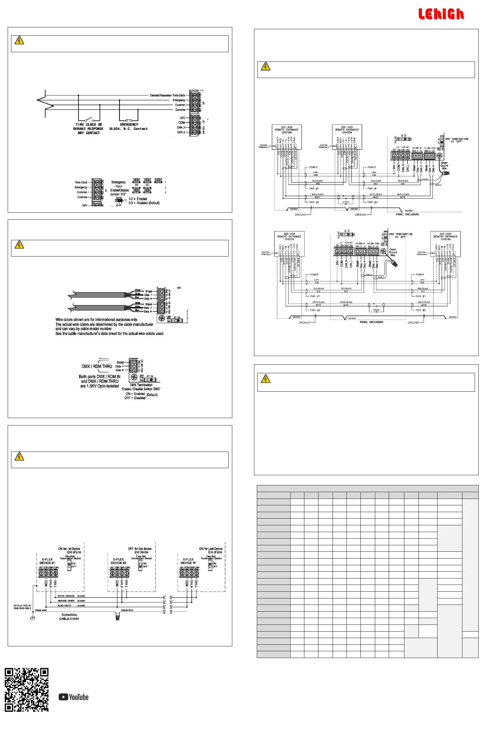
Impress Link Wiring
E-Flex can be configured to operate with Solitaire Impress remote wall stations to recall presets and provide
partitioned room control when each room has its own E-Flex Panel. The DMX input port is used for Impress
Link mode operation.
Recommend Belden 9729 or 9842 data cable with two twisted pairs.
RISK OF DEATH OR ELECTRIC SHOCK! Before wiring or servicing the unit, make sure
upstream source of power is off via a circuit breaker.
If the high voltage shield is removed, the panel must be accessed by a certified technician following local
codes.
FlexNet Wiring
#24-22 AWG wires, strip length – ¼ in., torque – 1.7 lbs.
Total distance should not exceed 1500 ft. between remote stations.
Wiring Diagram as End of Line
Wiring Diagram as Not End of Line
Configure Impress Link Mode, Assign Area and Zones
Impress Link mode, area, and zone assignment are set using the on-board user interface or E-Flex Flextool
Configurator software. Set area entry for (1-8) to enable this mode. See the E-Flex user manual for more
information.
RISK OF DEATH OR ELECTRIC SHOCK! Before powering up the unit for verification
checklist, make sure the high voltage shield in re-installed. Otherwise the panel
must be accessed by a certified technician.
This assumes the front cover is off the unit and the high voltage shield has been re-installed.
Verify the dip switch settings for occupancy and daylight sensors are correct.
Verify that DMX and FlexNet port termination is enabled or disabled as required for end of line
termination.
Verify that the emergency enable jumper is in the correct position if emergency contact closure
input is being used.
Turn on power from the circuit breaker(s) feeding the panel.
Ensure the power LED on the main controller board is lit. It is just to the left of the first zone relay.
FlexNet device ID setting – Setup per the E-Flex user manual and record on the ID label on the
front cover.
 Loading...