20 20
Prot menu (PAS)
Pro
Protection code
(PAS 99)
Prot Display Modification
0 SP, In2, alarms, OuP, INF SP, alarms
1 SP, In2, alarms, OuP, INF SP
2 SP, In2, OuP, INF
+ 4 to disable InP, Out
+ 8 to disable CFG, Ser,
+ 16 to disable SW “power-up - power down”
+ 32 disable manual power latching
+ 64 to disable manual power modification
+128 enables full configuration
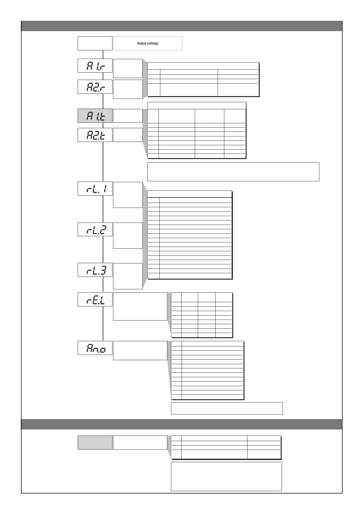
Out Menu
Out
Select reference
signal for
alarm 1
AL.1.r, AL.2.r
Select reference
signal for
alarm 2
AL.x.r Variable to be compared Reference setpoint
0 PV (Process variable) AL
1 SSP (active setpoint) AL (only absolute)
2 PV (process variable) AL (only relative and
referred to SP1 with
multiset function)]
Alarm type 1
Alarm type 2
+8 to disable on power up until first interception
+16 to latch alarm
+ 32 Hys becomes delay time when alarm trips (0...999 sec.) (excluding symmetrical absolute)
+ 64 Hys becomes delay time when alarm trips (0...999 min.) (excluding symmetrical absolute)
AL.x.t Direct (high limit) Absolute or Normal
Inverse (low limit) relative to
Symmetrical
active setpoint (window)
0 direct absolute normal
1 inverse absolute normal
2 direct relative normal
3 inverse relative normal
4 direct absolute
symmetrical
5 inverse absolute
symmetrical
6 direct relative
symmetrical
7 inverse relative
symmetrical
AL.1.t, AL.2.t
Default: 0
Default: 0
Default: 0
Default: 0
Fault action (sets state in case of
probe fault)
Err, Sbr
Val Reference value
0 PV - process variable
1 SSP - active setpoint
2 SP - local setpoint
3 -
4 Deviation (SSP-PV)
5 HEAT (*)
6 COOL (*)
7 AL1 (alarm point)
8 AL2 (alarm point)
9 AL3 (alarm point)
10 -
11 Value acquired from serial line (*)
Out W
Assignment of signal or reference
value
Out 1
Allocation of
reference signa
_rEL. Alarm Alarm Alarm
1 2 3
0 OFF OFF OFF
1 ON OFF OFF
2 OFF ON OFF
3 ON ON OFF
4 OFF OFF ON
5 ON OFF ON
6 OFF ON ON
7 ON ON ON
16 for code 0 if input is in error status Err – Sbr output assumes minimum
trimming value.
Out 2
Allocation of
reference signal
Out 3
Allocation of
reference signal
rL.o.1, rL.o.2, rL.o.3, rL.o.4
Val Function of main output relay/logic (OUT1)
0 HEAT (control output for heating)
1 COOL (control output for cooling)
2 AL1 - alarm 1
3 AL2 - alarm 2
4 AL3 - alarm 3
5 AL.HB - alarm HB
6 LBA - alarm LBA
7 IN1 - repetition of logic input
8 Repeat but key (if but = 8)
9 AL1 or AL2
10 AL1 or AL2 or AL3
11 AL1 and AL2
12 AL1 and AL2 and AL3
13 AL1 or ALHB
14 AL1 or AL2 or ALHB
15 AL1 and ALHB
16 AL1 and AL2 and ALHB
+ 32 for denied logic level at output, except codes 0…1 with continuous output
Default: 2
Default: 5
Default: 3
Default: 0
Default: 5