Potentiometer
Position
0 12345678910
Heating power %
OFF 10 20 30 40 50 60 70 80 90 100
Air volume l/min
200 270 340 410 480 550 620 690 760 830 900
Temperature (3680 W)
at 300 l/min °C
Environment 90 150 215 275 340 400 465 525 590 650
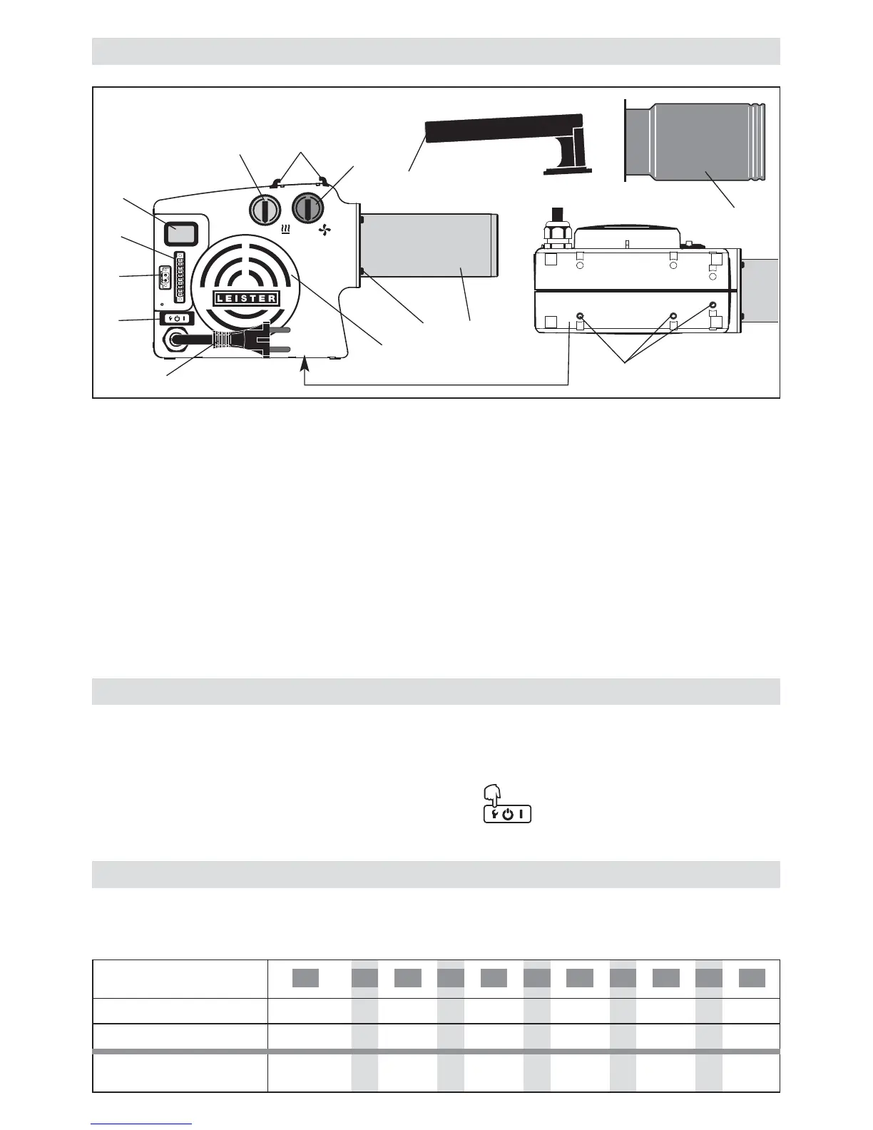
Device Description
HOTWIND PREMIUM or SYSTEM
1 Power supply cord
2 Main switch with function button
3 Potentiometer for temperature (red)
4 Potentiometer for air volume (blue)
5 Heating element tube
6 Air inlet flange for stainless steel filter
7 Holder for handle
8 Four fastening screws
9 Three M5 thread inserts for fastening
for installation
HOTWIND SYSTEM
10 Display
11 Alarm contact
12 Interface
HOTWIND PREMIUM hand device or SYSTEM
13 Handle
14 Protective tube
20
• If the heating element or device overheats (too hot inlet air or excess heat reside), the power supply to the
heating element will be interrupted and the working contact of the alarm relay opened.
If the heating element or device protection responds, it will be necessary to reset the HOTWIND for reasons
of safety. This occurs by pressing the function button (2) for three seconds. Check inlet air (see
installation).
Function of heating element and device protection
10
9
8
7
6
5
4
3
2
1
0
10
9
8
7
6
5
4
3
2
1
0
1
2
9
5
4
3
10
6
11
12
7
14
13
8
• The internal electronics regulates the maximum outlet air temperature to 650 °C.
• The reference values can be deviated from due to ambient conditions and component tolerances.
Adjustable potentiometer
 Loading...