Page 17
AC13 SERIES
SETTING UP TO CHECK CHARGE
1. Close manifold gauge set valves. Connect the center
manifold hose to an upright cylinder of HCFC−22.
2. Connect the manifold gauge set to the unit’s service
ports as illustrated in figure 3.
low pressure gauge to suction service port
high pressure gauge to liquid service port
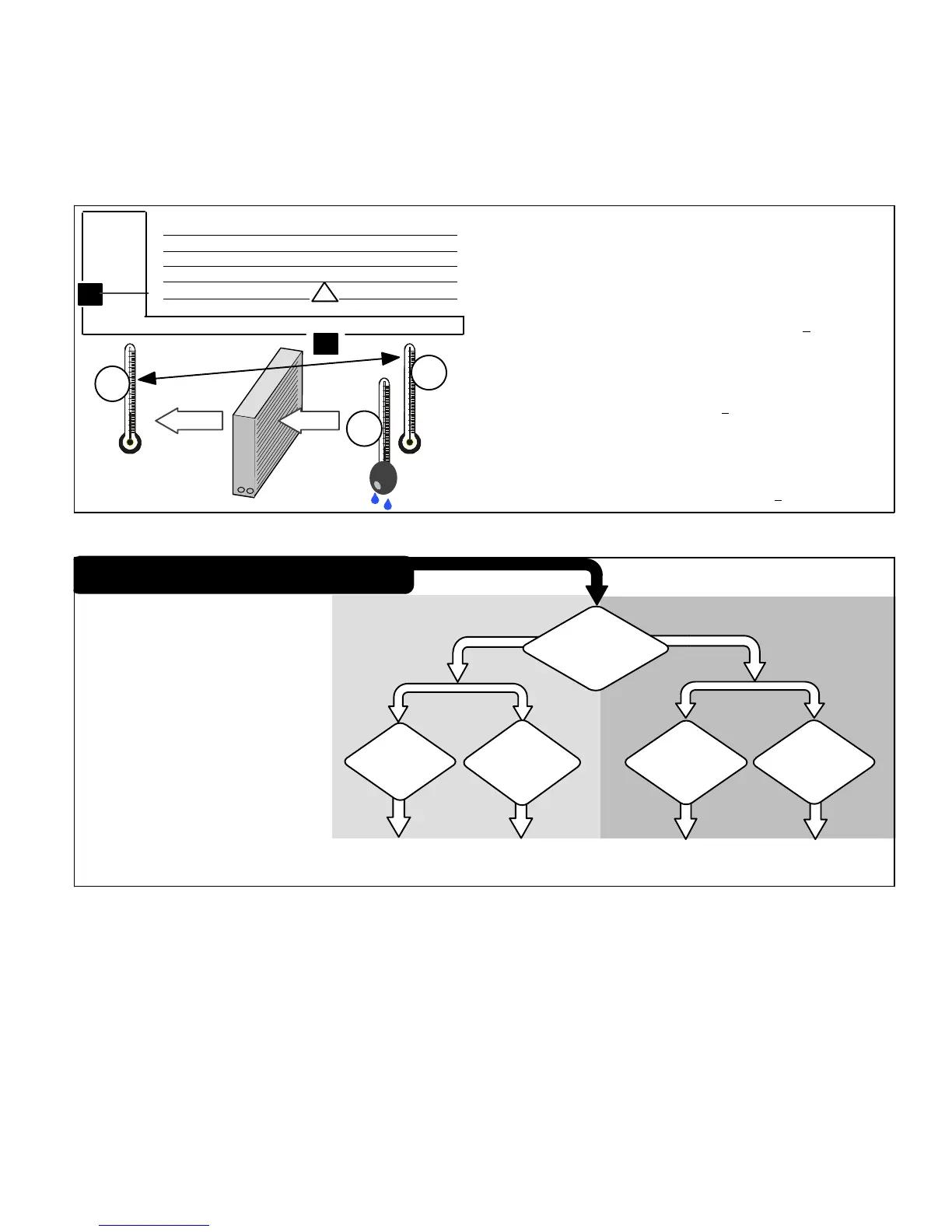
INDOOR AIRFLOW CHECK
Check indoor airflow using the Delta−T (
DT) process using
the illustration in figure 32.
DETERMINING CHARGE METHOD
Use the illustration in figure 33 to determine the correct
charging method.
1. Determine the desired DTMeasure entering air temperature
using dry bulb (A) and wet bulb (B). DT is the intersecting value of A
and B in the table (see triangle).
2. Find temperature drop across coilMeasure the coil’s dry bulb
entering and leaving air temperatures (A and C). Temperature Drop
Formula: (T
Drop
) = A minus C.
3. Determine if fan needs adjustmentIf the difference between the
measured T
Drop
and the desired DT (T
Drop
–DT) is within +3º, no ad-
justment is needed. See examples: Assume DT = 15 and A temp. =
72º, these C temperatures would necessitate stated actions:
Cº T
Drop
– DT = ºF ACTION
53º 19 – 15 = 4 Increase the airflow
58º 14 – 15 = −1 (within +3º range) no change
62º 10 – 15 = −5 Decrease the airflow
4. Adjust the fan speedSee indoor unit instructions to in-
crease/decrease fan speed.
Changing air flow affects all temperatures; recheck temperatures to
confirm that the temperature drop and DT are within +3º.
DT
80 24 24 24 23 23 22 22 22 20 19 18 17 16 15
78 23 23 23 22 22 21 21 20 19 18 17 16 15 14
76 22 22 22 21 21 20 19 19 18 17 16 15 14 13
74 21 21 21 20 19 19 18 17 16 16 15 14 13 12
72 20 20 19 18 17 17 16 15 15 14 13 12 11 10
70 19 19 18 18 17 17 16 15 15 14 13 12 11 10
57 58 59 60 61 62 63 64 65 66 67 68 69 70
Temp.
of air
entering
indoor
coil ºF
INDOOR
COIL
DRY
BULB
DRY
BULB
WET
BULB
B
T
Drop
19º
A
Dry−bulb
Wet−bulb ºF
A
72º
B
64º
C
53º
air flowair flow
All temperatures are
expressed in ºF
Figure 32. Checking Indoor Airflow over Evaporator Coil using Delta−T Chart
WHEN TO CHARGE?
Warm weather best
Can charge in colder weather
CHARGE METHOD? Determine by:
Metering device type
Outdoor ambient temperature
REQUIREMENTS:
Sufficient heat load in structure
Indoor temperature between 70-80ºF
(21−26ºC)
Manifold gauge set connected to unit
Thermometers:
− to measure outdoor ambient
temperature
− to measure liquid line temperature
− to measure suction line
temperature
TXV
RFC
APPROACH OR
SUBCOOLING
WEIGH-INSUPERHEAT
65ºF
(18.3ºC) and
Above
START: Determine how refrigerant is metered
39ºF
(3.8ºC) and
Below
Which
metering
device?
WEIGH-IN
64ºF
(17.7ºC) and
Below
40ºF
(4.4ºC) and
Above
Figure 33. Determining Charge Method
 Loading...