Page 32
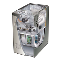
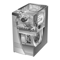
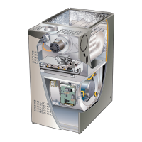
Cleaning the Heat Exchanger and Burners
NOTE - Use papers or protective covering in front of the
furnace during cleaning.
1 - Turn o both electrical and gas power supplies to
furnace.
2 - Remove ue pipe and top cap (some applications
top cap can remain) from the unit.
3 - Label the wires from gas valve, rollout switches,
primary limit switch and make-up box then
disconnect them.
4 - Remove the screws that secure the combustion air
inducer/ pressure switch assembly to the collector
box. Carefully remove the combustion air inducer
to avoid damaging blower gasket. If gasket is
damaged, it must be replaced to prevent leakage.
5 - Remove the collector box located behind the
combustion air inducer. Be careful with the collector
box gasket. If the gasket is damaged, it must be
replaced to prevent leakage.
6 - Disconnect gas supply piping. Remove the screw
securing the burner box cover and remove cover.
Remove the four screws securing the burner
manifold assembly to the vestibule panel and
remove the assembly from the unit.
7 - Remove screws securing burner box and remove
burner box.
8 - NOX units only - Remove screw securing NOX
insert. Remove NOX insert. FIGURE 25.
9 - Remove screws from both sides, top and bottom of
vestibule panel.
10 - Remove heat exchanger. It may be necessary
to spread cabinet side to allow more room. If so,
remove ve screws from the left side or right side of
cabinet. See FIGURE 26.
11 - Backwash using steam. Begin from the burner
opening on each clam. Steam must not exceed
275°F.
12 - To clean burners, run a vacuum cleaner with a soft
brush attachment over the face of burners. Visually
inspect inside the burners and crossovers for any
blockage caused by foreign matter. Remove any
blockage. FIGURE 24 shows burner detail.
13 - To clean the combustion air inducer visually inspect
and using a wire brush clean where necessary. Use
compressed air to clean o debris and any rust.
14 - Reinstall heat exchanger in vestibule. (Replace the
ve screws in the cabinet from step 10 if removed).
15 - NOx units only - Replace NOx inserts.
16 - Reinstall collector box and combustion air
assembly. Reinstall all screws to the collector box
and combustion air inducer. Failure to replace all
screws may cause leaks. Inspect gaskets for any
damage and replace ifw necessary.
17 - Reinstall burner box, manifold assembly and burner
box cover.
18 - Reconnect all wires.
19 - Reconnect top cap and vent pipe to combustion air
inducer outlet.
20 - Reconnect gas supply piping.
21 - Turn on power and gas supply to unit.
22 - Set thermostat and check for proper operation.
23 - Check all piping connections, factory and eld, for
gas leaks. Use a leak detecting solution or other
preferred means.
WARNING
Some soaps used for leak detection are corrosive
to certain metals. Carefully rinse piping thoroughly
after leak test has been completed. Do not use
matches, candles, ame or other sources of ignition
to check for gas leaks.
24 - If a leak is detected, shut gas and electricity o and
repair leak.
25 - Repeat steps 24 and 26 until no leaks are detected.
26 - 26 -Replace access panel.
 Loading...