Page 13
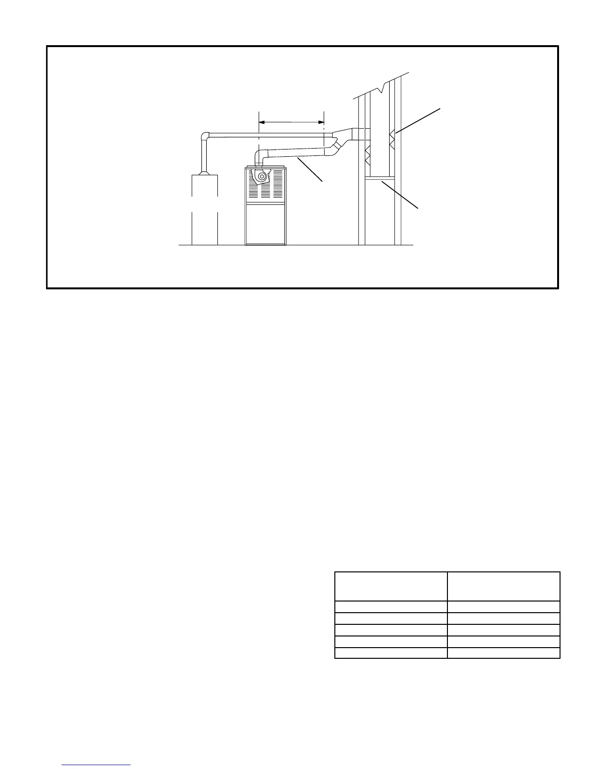
Common Venting Using Tile-lined Interior Masonry
Chimney
and Combined Vent Connector
G24M
OTHER
APPLIANCE
MINIMUM LENGTH = AS SHORT AS PRACTICAL.
FOR MAXIMUM LENGTH SEE NOTE TO LEFT
INTERIOR TILE-LINED
MASONRY CHIMNEY
NOTE - chimney must be properly
sized per provided venting tables
or lined with listed metal lining
system.
PERMANENTLY
SEALED FIREPLACE
OPENING
VENT
CONNECTOR
SEE NOTE 1 BELOW
Note 1 - Either singleĆwalled or doubleĆwalled vent connector may be used. Refer to the capacity requirements as shown in the proĆ
vided venting tables for installations in USA and the venting tables in current CAN/CGA-B149.1 for installations in Canada.
NOTE- Refer to provided venting tables
for installations in the USA and the
venting tables in current CAN/CGA-
B149.1 for installations in Canada.
FIGURE 15
General Venting Requirements
All G24M furnaces must be vented according to these
instructions.
1 - Vent diameter recommendations and maximum alĆ
lowable piping runs are found in the provided venting
tables for the USA, and the appropriate venting tables
in the standards of CAN/CGA B149.1 and B149.2 of
the Natural Gas and Propane Installation Code for
Canada.
2 - In no case should the vent or vent connector diameter
be less than the diameter specified in the provided
venting tables for the USA, and the appropriate ventĆ
ing tables in the standards of CAN/CGA B149.1 and
B149.2 of the Natural Gas and Propane Installation
Code for Canada.
3 - For single appliance vents: If the vertical vent or tileĆ
lined chimney has a larger diameter or flow area than
the vent connector, use the vertical vent diameter to
determine the minimum vent capacity and the vent
connector diameter to determine the maximum
vent capacity. The flow area of the vertical vent, howĆ
ever, shall not exceed 7 times the flow area of the
listed appliance categorized vent area, drafthood outĆ
let area or flue collar area unless designed according
to approved engineering methods.
4 - For multiple appliance vents: The flow area of the largĆ
est section of vertical vent or chimney shall not exceed
7 times the smallest listed appliance categorized vent
area, drafthood outlet area or flue collar area unless
designed according to approved engineering methĆ
ods.
5 - The entire length of single wall metal vent connector
shall be readily accessible for inspection, cleaning,
and replacement.
6 - Single appliance venting configurations with zero latĆ
eral lengths, see tables 4 and 5, are assumed to have
no elbows in the vent system. For all other vent configĆ
urations, the vent system is assumed to have two 90_
elbows. For each additional 90_ elbow or equivalent
(for example two 45_ elbows equal one 90_ elbow) beĆ
yond two, the maximum capacity listed in the venting
table should be reduced by 10 percent (0.90 x maxiĆ
mum listed capacity).
7 - The common venting tables 6, 7, 8, and 9 were generĆ
ated using a maximum horizontal vent connector
length of 1-1/2 feet (.46 m) for each inch (25 mm) of
connector diameter as follows:
TABLE 3
Connector
Diameter
inches (mm)
Maximum Horizontal
Connector Length
feet (m)
3 (76) 4-1/2 (1.37)
4 (102) 6 (1.83)
5 (127) 7-1/2 (2.29)
6 (152) 9 (2.74)
7 (178) 10-1/2 (3.20)

 Loading...


