Page 12
FIGURE 13
*This reducer is not necessary for G26-50 units using 1-1/2 in. venting.
See venting table 4 for maximum venting lengths with this arrangement.
12 (305) ABOVE
AVERAGE SNOW
ACCUMULATION
UNCONDITIONED
SPACE
12 (305) MIN. for 2 (51)
20 (508) MAX. for 3 (76)
8 (203)
MIN.
1/2 (13) FOAM
INSULATION
1/2 (13) FOAM
INSULATION IN
UNCONDITIONED
SPACE
PROVIDE SUPPORT
FOR INTAKE AND
EXHAUST LINES EVERY
36 (914)
OUTSIDE WALL
Inches(mm)
SIDE VIEW
WALL RING TERMINATION
(15F74) LB-49107CB for 2 in. (51) Venting
9 - Position termination ends so they are free from any obĆ
structions and above the level of snow accumulation
(where applicable). Termination ends must be a mini-
mum of 12 inches (305mm) above grade level. Do not
point into window wells, stairwells, alcoves, courtyard
areas or other recessed areas. Do not position terminaĆ
tion ends directly below roof eaves or above a walkway.
Since the G26 is a certified direct vent, Category IV gas
furnace, the location of the termination is limited by loĆ
cal building codes. In the absence of local codes, refer
to the current National Fuel Gas Code ANSI Z223-1 in
U.S.A., and current standards CAN/CGA-B149.1 /.2 of
the Natural Gas and Propane Installation Instructions in
Canada for details. The termination should be at least
12 inches (305mm) from any opening through which
flue products could enter the building.
When horizontally vented, minimum clearance for terĆ
mination from electric meters, gas meters, regulators
and relief equipment is 4 feet (1.2m) for US installaĆ
tions. Refer to the current CAN/CGA-B149.1 and .2 for
installations in Canada or with authorities having local
jurisdiction.
At vent termination, care must be taken to maintain
protective coatings over building materials (proĆ
longed exposure to exhaust condensate can destroy
protective coatings). It is recommended that the exĆ
haust outlet not be located within 6 feet (1.8m) of a
condensing unit because the condensate can damĆ
age the painted coating.
IMPORTANT
Combustion air intake inlet and exhaust outlet should
not be located within 6 feet (1.8m) of dryer vent or comĆ
bustion air inlet or outlet of another appliance. Piping
should not exit less than 3 feet (.91m) from opening
into another building.
IMPORTANT
For Canadian Installations Only:
In accordance to CAN/CGA-B149.1 and .2, the miniĆ
mum allowed distance between the combustion air
intake inlet and the exhaust outlet of other apĆ
pliances shall not be less than 12 inches (305mm).
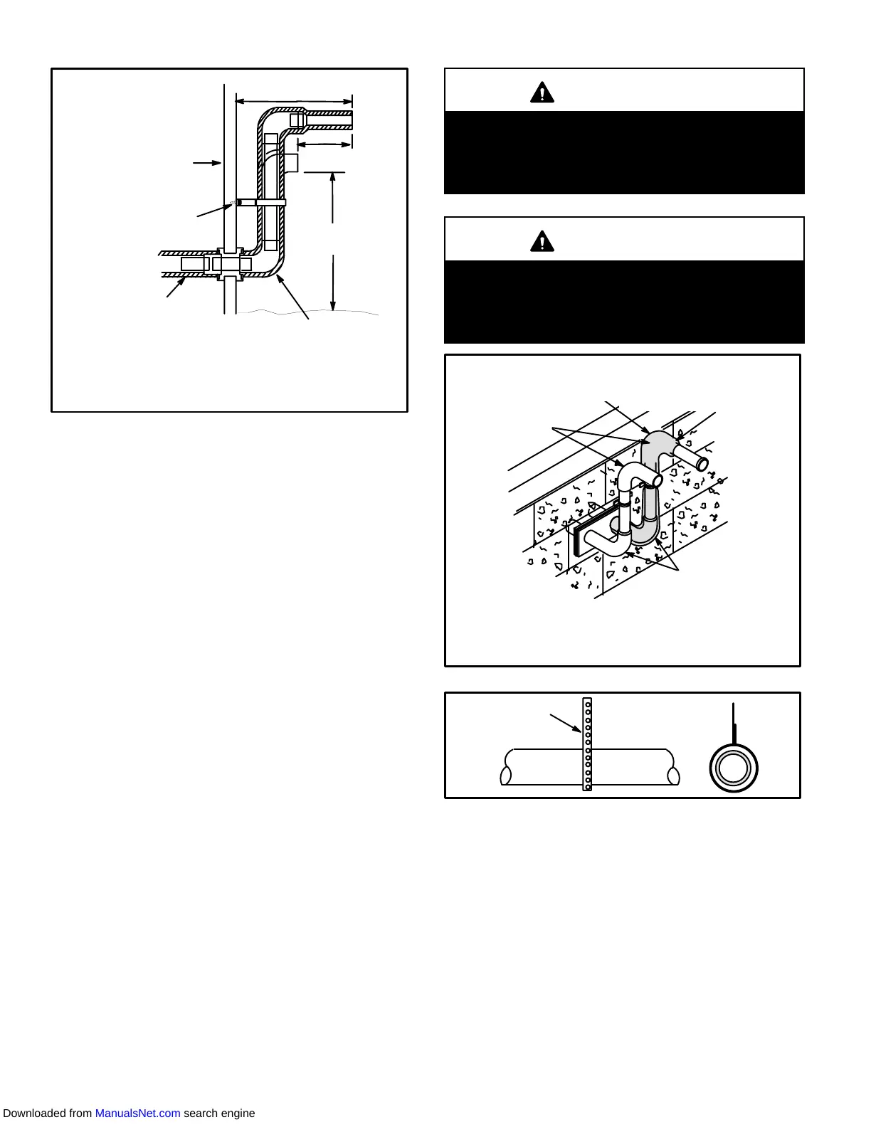
FIGURE 14
Inches (mm)
FRONT VIEW
WALL TERMINATION
(22G44) LB-49107CD for 2(51) Venting
(44J40) LB-65701A for 3(76) Venting
3 (76) OR
2 (51) 90° ELBOW
1/2 (13)
FOAM
INSULATION
Inches(mm)
3 (76) OR
2 (51) 90° ELBOW
3 x 2 (76 x 51) OR
2 x 1-1/2 (51 x 38)
REDUCER BUSHING LOCATION
FOR OFFSET TERMINATION
Optional Turndown
(Not Shown)
May Be Used on
Intake Only
FIGURE 15
METAL OR PLASTIC
STRAPPING
OR LARGE WIRE TIES
10 - Suspend piping using hangers at a minimum of every
5 feet (1.52m) for schedule 40 PVC and every 3 feet
(.91m) for ABS-DWV, PVC-DWV, SPR-21 PVC, and
SDR-26 PVC piping. A suitable hanger can be fabriĆ
cated by using metal or plastic strapping or a large
wire tie.
11 - In areas where piping penetrates joists or interior
walls, hole must be large enough to allow clearance on
all sides of pipe through center of hole using a hanger.
12 - Isolate piping at the point where it exits the outside wall
or roof.
Downloaded from ManualsNet.com search engine
 Loading...

