Page 14
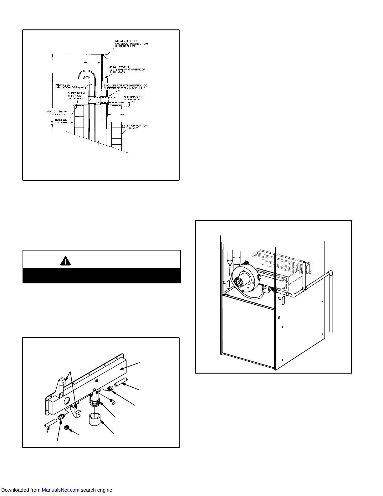
G26 VENTING IN EXISTING CHIMNEY
NOTE-Do not discharge exhaust gases directly into any chimney or vent stack. If vertiĆ
cal discharge through an existing unused chimney or stack is required, insert piping
inside chimney until the pipe open end is above top of chimney and terminate as illusĆ
trated. In any exterior portion of chimney, the exhaust vent must be insulated. An alterĆ
nate method is to fill the chimney with vermiculite or equal to take advantage of its
acoustic and thermal properties.
FIGURE 20
8 in. - 12 in.
(203mm - 305mm)
3 in. - 8 in.
(76mm-
203mm)
3 in. - 8 in.
(76mm-
203mm)
Condensate Piping
This unit is designed for either right- or left-side exit of conĆ
densate piping. Condensate drain line should be routed
only within the conditioned space to avoid freezing of conĆ
densate and blockage of drain line. An electric heat cable
should be used where condition is exposed to uncondiĆ
tioned areas.
CAUTION
Do not use copper tubing or existing copper condenĆ
sate lines for drain line.
1 - Determine which side condensate will exit the unit.
2 - Connect a 1/2 inch (13mm) plastic pipe plug (provided)
in the unused end of the condensate trap. Install plug so
that it is sealed water tight yet able to be removed. Do
not permanently seal the connection. Teflon tape is recĆ
ommended to seal joint. See figure 21.
CONDENSATE ASSEMBLY
(For left or right installation)
FIGURE 21
COLD HEADER
BOX
NIPPLE
ADAPTER
ADAPTER
NIPPLE
PLUG
BOOT OR CAP
COMBUSTION AIR
INDUCER BRACKET
CONDENSATE TRAP
3 - Use the provided adapter (1/2 inch PVC x 1/2 inch
MPT) and the nipple (1/2 inch PVC) to carry drainage
outside the cabinet. If a field substitute is needed, 1/2
inch CPVC x 1/2 inch MPT adapter and 1/2 inch CPVC
is acceptable for use.
4 - Glue nipple to the adapter using the procedures out-
lined in the Joint Cementing Procedures" section.
The nipple/adapter assembly should be connected in
a non-permanent manner and must be water tight.
Teflon tape is recommended to seal the joint.
For Right-Hand Side Condensate Exit:
Install the nipple/adapter assembly from the outside
of the cabinet and insert the adapter into the threaded
opening in the condensate trap.
For Left-Hand Side Condensate Exit:
Insert nipple/adapter assembly from the left hand
side of the cabinet and through the combustion air
inducer mounting structure into the threaded openĆ
ing in the condensate trap.
5 - Connect field supplied plumbing to nipple and route to
open drain. Plumbing should be vented to a point higher
than the condensing coil. See figure 22.
FIGURE 22
CONDENSATE PLUMBING
(Plumbing must be vented higher than coil.)
6 - Connect condensate drain line (1/2 inch [13mm] SDR
11 plastic pipe or tubing) to condensate connection on
drip leg assembly and route to open drain. Conden-
sate line must be sloped downward away from drip leg
to drain. If drain level is above drip leg, condensate
pump must be used to condensate line. Condensate
drain line should be routed within the conditioned
space to avoid freezing of condensate and blockage of
drain line. If this is not possible, a heat cable kit may be
Downloaded from ManualsNet.com search engine
 Loading...

