Page 6
FIGURE 3
G26 UNIT
SUPPLY AIR
PLENUM
PROPERLY
SIZED FLOOR
OPENING
BOTTOM RETURN AIR APPLICATION
NOTE - Be careful not to damage glass fiber insulation.
Check for tight seal.
Side Return Air Applications
For installations where the return air is taken from a return
air drop, unit may be installed using either the left or right
side of furnace.
For side return air applications, cut furnace cabinet at the
dimensions given on page 2. Embossed corners are proĆ
vided on both cabinet sides for return air opening location.
Filters & Optional Filter Assembly
This unit is not equipped with a filter. Filter racks and re-
usable foam filters are available from Lennox in single
kits (44J20 for 14 x 25 filters; 44J21 for 20 x 25 filters) or
10-pack kits (66K61 for 14 x 25 filters; 66K62 for 20 x 25
filters). A filter must be in place anytime the unit is in opĆ
eration.
Bottom Return Air Applications
1 - Remove blower access panel.
2 - Install filter clips, provided with unit, by slipping folded
section of clip on edge of bottom opening. See figure 4.
3 - Place filter in bottom of blower compartment beneath
rear filter clip. Press down on filter sides. Filter clips flex
allowing filter to snap into place.
4 - To remove filter, press clip and pull filter up and out.
FIGURE 4
BOTTOM RETURN FILTER INSTALLATION
FURNACE
BASE BOTTOM
REAR FILTER CLIP
RETURN AIR OPENING
SIDE FILTER CLIPS (2)
FURNACE
FRONT
FURNACE
BACK
Side Return Air Applications
An external filter rack, ordered separately, is available from
Lennox.
NOTE - The filter door may be shipped in the rack behind
the filter. If necessary, remove the filter, retrieve the door
and continue with the installation of the rack.
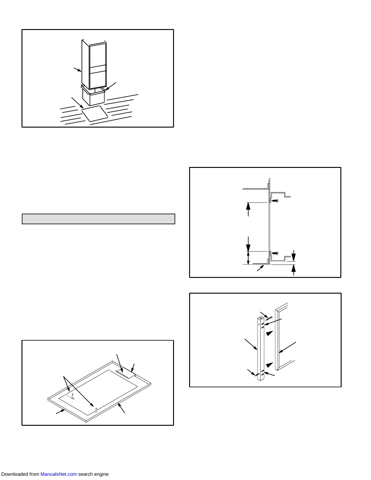
1 - Align filter rack opening with the inside edge of the side
return opening. Bottom of rack should be approxiĆ
mately 1 inches (25mm) from the bottom and 3 inch-es
(76mm) from the front of the unit.
2 - Screw filter rack into place with the eight self-drilling,
self-tapping screws provided. See figure 5.
3 - Push filter door pins through the two holes in filter door
from the inside of the u-channel. See figure 6.
4 - Position filter door on end of filter so that the thumb tab
side of the filter door is away from the furnace. Squeeze
thumb tabs to secure filter to door.
FIGURE 5
SIDE RETURN FILTER INSTALLATION
RETURN
AIR
OPENING
12 in. (305) for
14 in. (356) Filter
18 in. (457) for
20 in. (508) Filter
1-15/16 in.
(49)
BLOWER DECK
15/16 in.
(24)
CABINET BASE BOTTOM
RETURN AIR
PLENUM SIZE
12-3/4 in. X 23-1/2 in. (324 X 597)
for 14 in. (356) Filter
18-3/4 in. x 23-1/2 in. (476 x 597)
for 20 in. (508) Filter
FIGURE 6
FILTER DOOR ASSEMBLY
FILTER DOOR
PINS
FILTER DOOR
FILTER
FILTER DOOR
PIN
TAB
TAB
5 - Guide filter and filter door into the filter rack installed on
side of furnace. Push door into filter rack until secure.
6 - To remove filter, pull filter door pins until door is re-
leased from filter rack.
Downloaded from ManualsNet.com search engine
 Loading...

