Page 35
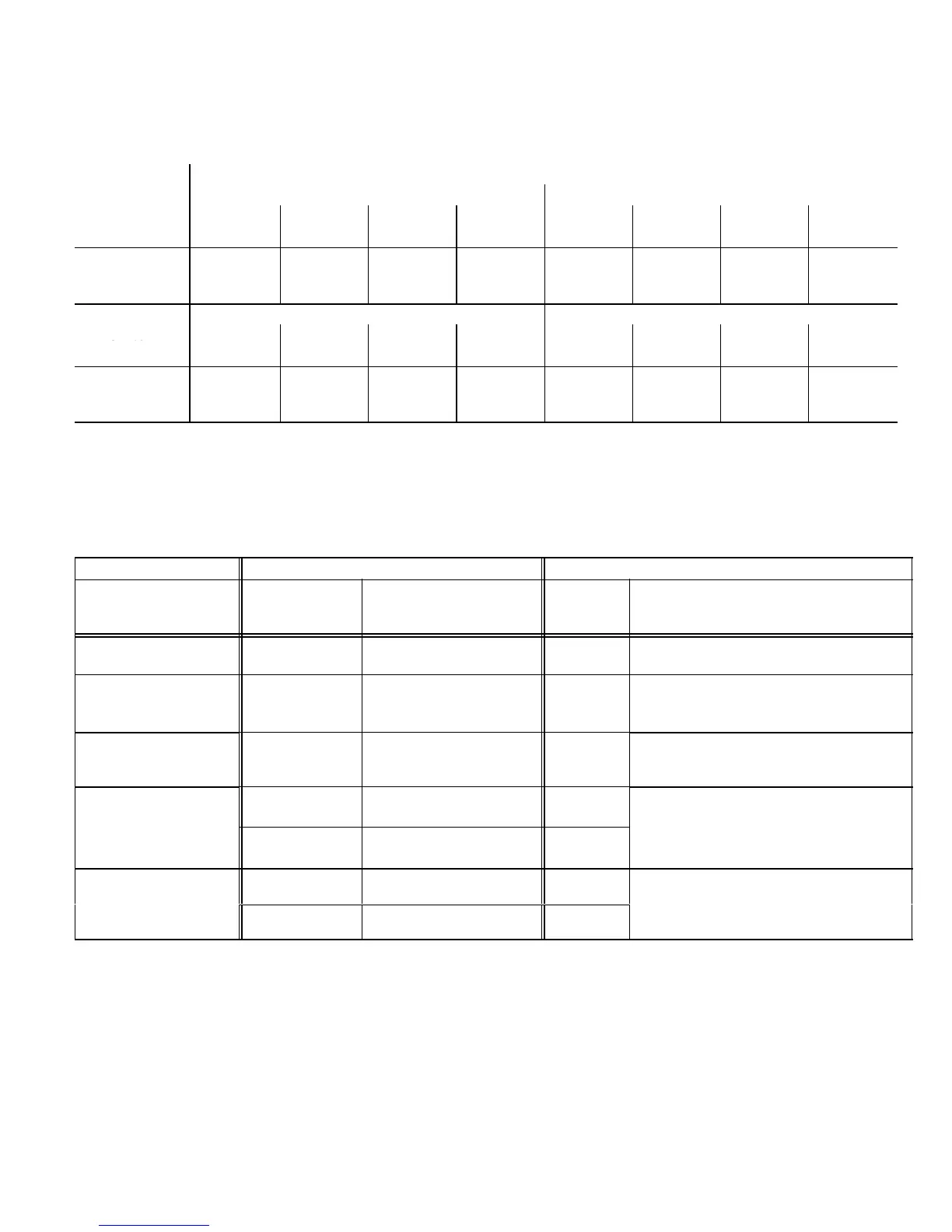
TABLE 26
G60UHV−60D−135 BLOWER MOTOR PERFORMANCE
0.0" to 0.8" w.g. (0 through 200 Pa) External Static Pressure Range
Factory Settings: Heating Speed − 2; Cooling Speed − 4; Speed Adjust − NORM.
Return Air Options: Side return air with optional RAB return air base.
Speed Switch Positions
ADJUST"
Second Stage HEAT" Speed Second Stage COOL" Speed
Switch
Positions
1 2 3 4 1 2 3 4
cfm L/s cfm L/s cfm L/s cfm L/s cfm L/s cfm L/s cfm L/s cfm L/s
+
1425 675 1615 760 1795 845 1975 930 1505 710 1620 765 1815 855 2035 960
NORM N/A N/A 1455 690 1640 775 1805 850 1370 650 1470 695 1670 790 1850 875
N/A
N/A N/A N/A 1455 685 1630 770 1225 580 1320 625 1500 705 1670 790
"
First Stage HEAT" Speed First Stage COOL" Speed
Positions
cfm
L/s cfm L/s cfm L/s cfm L/s cfm L/s cfm L/s cfm L/s cfm L/s
+
1305 615 1470 695 1655 780 1825 860 1075 510 1155 545 1295 610 1445 680
NORM N/A N/A 1345 635 1505 710 1670 790 980 465 1050 495 1175 555 1305 615
N/A N/A N/A N/A 1340 635 1475 695 875 415 935 440 1070 505 1180 555
N/A − First and second stage HEAT positions shown cannot be used on this model.
NOTES − The effect of static pressure is included in air volumes shown.
First stage HEAT is approximately 91% of the same second stage HEAT speed position.
First stage COOL (two−stage air conditioning units only) is approximately 70% of the same second stage COOL speed position.
Continuous Fan Only speed is approximately 38% of the same second stage COOL speed position − minimum 500 cfm (235 L/s).
Lennox Harmony IIIt Zone Control Applications − Minimum blower speed is 495 cfm (235 L/s).
TABLE 27
OPERATING SEQUENCE
G60UHV, Thermostat with Humidity Control Feature and Single−Speed Outdoor Unit
OPERATING MODE SYSTEM DEMAND SYSTEM RESPONSE
System Condition
Thermostat
Demand
*Relative Humidity
(EfficiencyPlus Lights)
Blower
CFM
(COOL)
Comments
Normal operation Y1
No demand. Humidity
level is acceptable
COOL
Compressor demand and indoor blower
speed controlled by thermostat demand.
*Call for humidity
removal during
cooling demand
Y1
Humidity level rises
above setpoint. Demand
initiated.
60%/65%
of COOL
Call for dehumidification initiated by ther-
mostat. Indoor blower speed reduced by
thermostat.
Dehumidification
demand satisfied
during cooling de-
mand.
Y1
Humidity level falls below
setpoint. No demand
COOL
When humidity demand is satisfied, blow-
er speed immediately increases to the
COOL CFM to hasten the end of the cycle.
Call for cooling after
None
Humidity level above set-
point. Demand initiated.
Off
Dehumidification mode begins when rela-
call for humidity
removal.
Y1
Humidity level above set-
point. Demand initiated.
60%/65%
of COOL
tive humidity is greater than setpoint.
Humidity demand
satisfied between
None Over setpoint (1 or more) Off
While unit is not operating (no thermostat
demand) slide switch is moved down and
thermostat demands
(unit off cycle).
Y1 Change to acceptable COOL
back up. Blower operates at COOL CFM.
NOTE − When changing unit mode of operation from cooling to heating, indicating lights that are on will stay on until the first ther-
mostat heating demand.
* Reduced blower speed is 65% of COOL for the −36A and −36B units; 60% of COOL for −60C and −60D series units.

 Loading...


