Page 41
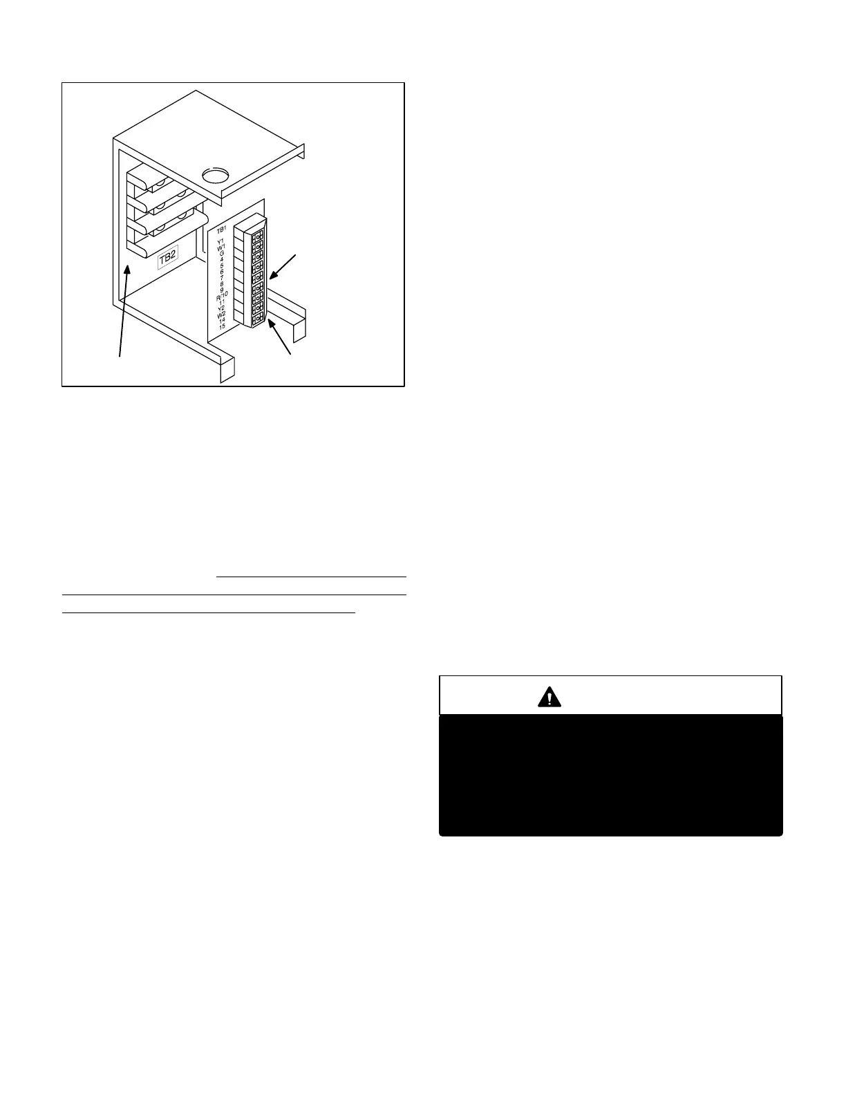
FIGURE 39
MAKE-UP BOX
12.5 TON AND LARG
ER UNITS ONLY
LOW VOLTAGE
TERMINAL STRIP TB1
LINE VOLTAGE
TERMINAL STRIP TB2
TO INSERT OR RELEASE
WIRE, DEPRESS CEN
TER
WITH PEN OR SMALL
SLOT SCREWDRIVER .
2-Line Voltage Make-Up Strip TB2
Line voltage terminal strip TB2 (figure 39) is provided in all
GCS16 series units to provide a means for connection of
all line voltage wiring. Knock-outs provided in the base pan
of the unit cabinet allow for passage of wires into conduit
and roof mounting frame. In 10 ton and smaller units, TB2
is located in the unit control box. In 12.5 ton and larger
units, TB2 is located in the blower compartment.
3-Low Voltage Terminal Strip TB1
All GCS16 units are equipped with a low voltage terminal
strip TB1. In 10 ton and smaller units, TB1 is located in the
unit control box. In 12.5 ton and larger units, TB1 is located
in the blower compartment (figure39). Most low voltage
(thermostat) electrical connections can be made to this
terminal strip. Knock-outs provided in the base pan of the
unit cabinet allow for passage of wires into conduit and
roof mounting frame. Special instructions are provided
where needed for low voltage connections that cannot be
made to the terminal strip. A detail drawing of TB1 is also
shown in figure 10.
III-ELECTRICAL CONNECTIONS
A-Power Supply
Refer to startup directions and refer closely to the unit wir
ing diagram when servicing. See unit nameplate for mini
mum circuit ampacity and maximum fuse size.
208/460/575 volt units are factory wired with red wire con
nected to control transformer primary. 230 volt units are
field wired with orange wire connected to control trans
former primary.
IV-PLACEMENT AND INSTALLATION
Make sure that the unit is installed in accordance with the
installation instructions and all applicable codes. See ac
cessories section for conditions requiring use of the op
tional roof mounting frame (RMF16).
V-STARTUP - OPERATION
A-Preliminary and Seasonal Checks
1- Make sure the unit is installed in accordance with the
installation instructions and applicable codes.
2- Inspect all electrical wiring, both field and factory
installed for loose connections. Tighten as required.
Refer to unit diagram located on inside of unit control
box cover.
3- Check to ensure that refrigerant lines are in good con
dition and do not rub against the cabinet or other re
frigerant lines.
4- Check voltage at the disconnect switch. Voltage must
be within the range listed on the nameplate. If not, con
sult the power company and have the voltage cor
rected before starting the unit.
5- Recheck voltage and amp draw with unit running. If
power is not within range listed on unit nameplate,
stop unit and consult power company. Refer to unit
nameplate for correct running amps.
6- Inspect and adjust blower belt (see section
VIII-C-Blower Belt Adjustment).
B-Cooling Startup
NOTE-The following is a generalized procedure and
does not apply to all thermostat control systems. Elec
tronic and ramping thermostat control systems may op
erate differently. Refer to the operation sequence sec
tion of this manual for more information.
WARNING
Crankcase heaters must be energized for 24
hours before attempting to start compressors.
Set thermostat so there is no compressor demand
before closing disconnect switch. Attempting to
start compressors during the 24hour warmup
period could result in damaged or failed compres
sors.
1- Set fan switch to AUTO or ON and move the system
selection switch to COOL. Adjust the thermostat to a
setting far enough below room temperature to bring
on all compressors. Compressors will start and cycle
on demand from the thermostat (allowing for unit and
thermostat time delays).
2- Each refrigerant circuit is charged with R-22 refrigerant.
See unit rating plate for correct charge amount.
3- Refer to Cooling Operation and Adjustment section
for proper method of checking charge.
 Loading...
