Page 42
C-Heating Startup
1- Set thermostat to OFF position. Close manual knob
on gas valve(s).
2- Wait five minutes.
3- Open manual knob on gas valve(s), replace burner
access door and turn on unit electrical supply.
4- Set the fan switch to AUTO or ON and move the sys
tem selection switch to HEAT. Adjust the thermostat
setting above room temperature.
5- The combustion air blower immediately starts. The
burners light within 40 sec.
6- If the burners do not light the first time, it will attempt up
to two more times before locking out.
7- If lockout occurs, repeat the previous steps.
D-Safety or Emergency Shutdown
Turn off power to the unit.
VI-COOLING SYSTEM SERVICE CHECKS
GCS16 is factory charged and requires no further adjust
ment; however, charge should be checked periodically us
ing the approach method. The approach method
compares actual liquid temperature with the outdoor ambi
ent temperature. Thermometer wells have been provided
to allow accurate liquid temperature measurement.
A-Gauge Manifold Attachment
Service gauge ports are identified in figures 31 and 32. At
tach high pressure line to liquid line gauge port on ther
mometer well. Attach low pressure line to suction line ser
vice port.
B-Charging
This unit is factory charged and requires no further adjust
ment; however, check charge during start-up using the ap
proach method outlined below. The approach method
compares actual liquid temperature with the outdoor ambi
ent temperature. Thermometer wells have been provided
to allow accurate liquid temperature measurement.
If the system is completely void of refrigerant, the recom
mended and most accurate method of charging is to weigh
refrigerant into the unit according to the amount shown on
the unit nameplate and in the specifications table. If weighing
facilities are not available or if the unit is just low on charge,
use the following procedures:
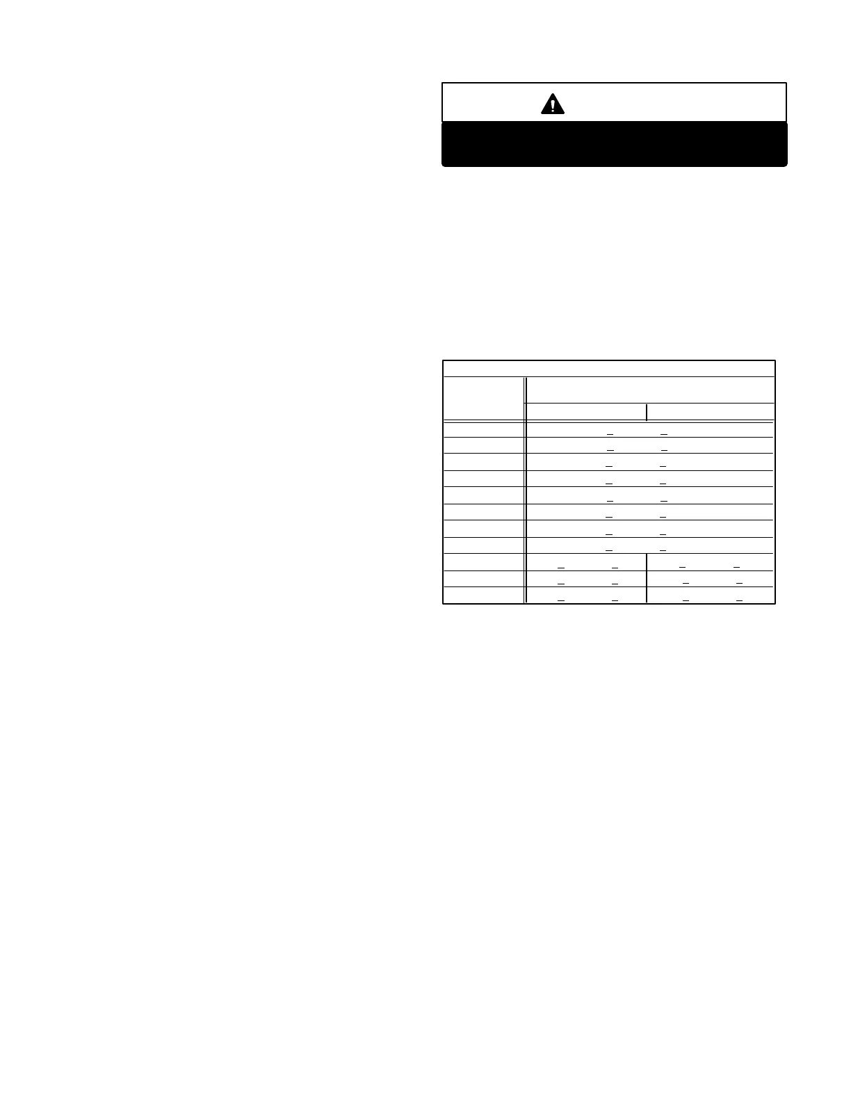
WARNING
Do not exceed nameplate charge under any con
ditions. Compressor damage will result.
1- This method uses a thermometer inserted in the ther
mometer wells to check liquid line temperature. Make
sure thermometer wells are filled with oil before
checking.
2- IMPORTANT - Block compressor compartment with
access panel so air will not by-pass the coils.
3- Operate unit (all compressors) for at least five minutes
until pressures stabilize.
TABLE 6
APPROACH TEMPERATURE
UNIT Degrees F Liquid Line Warmer Than
Outdoor Air
GCS16-1853 7°F + 1 (3.9°C + 0.5)
GCS16823 7°F + 1 (3.9°C + 0.5)
GCS16953 8°F + 1 (4.5°C + 0.5)
6°F + 1 (3.3°C + 0.5)
6°F + 1 (3.3°C + 0.5)
GCS161353
GCS161603
7°F + 1 (3.9°C + 0.5)GCS162553*
7°F + 1 (3.9°C + 0.5)GCS162753*
7°F + 1 (3.9°C + 0.5)GCS163003*
7°F + 1 (3.9°C + 0.5)GCS162553
1st Stage 2nd Stage
8°F + 1 (4.5°C + 0.5)
8°F + 1 (4.5°C + 0.5)GCS162753
10°F + 1 (5.6°C + 0.5)
GCS163003
*Round cornered condenser coils.
Slab type condenser coils.
10°F + 1 (5.6°C + 0.5)9°F + 1 (5.1°C + 0.5)
4- Check each stage separately with all stages operat
ing. Compare liquid temperatures to outdoor ambient
temperature. Liquid line temperature should be a few
degrees warmer than the outdoor air temperature.
Table 6 shows how much warmer the liquid line should
be. For best results use same thermometer for both
readings.
Add refrigerant to make the liquid line cooler. Recover
refrigerant to make the liquid line warmer.
VII-HEATING SYSTEM SERVICE CHECKS
A-A.G.A./C.G.A. Applications
and Requirements
All GCS16s are A.G.A and C.G.A. design certified without
modification.
 Loading...
