Page 43
Before checking piping, check with gas company or au
thorities having jurisdiction for local code requirements.
Refer to the GCS16 Operation and Installation Instruction
Manual for more information.
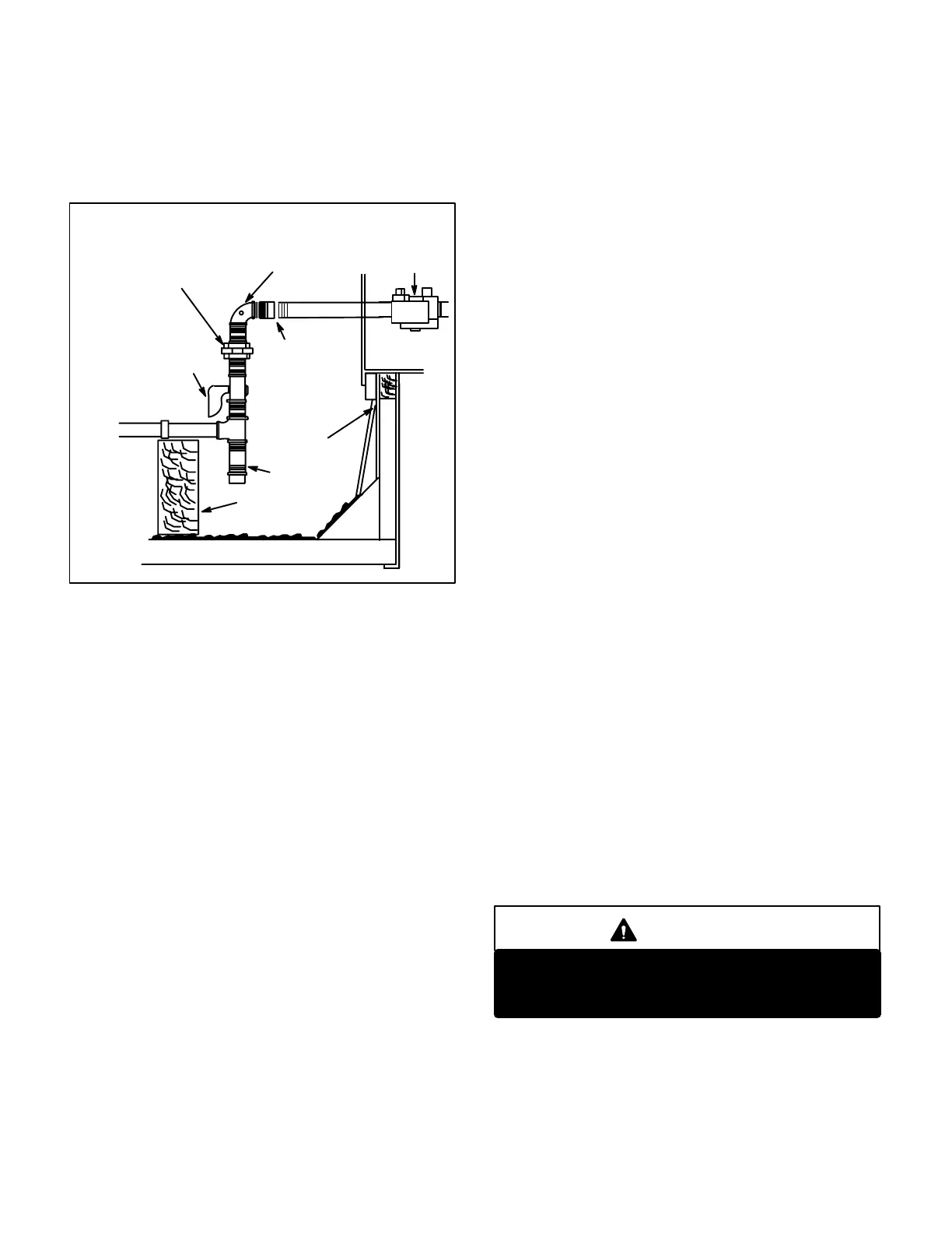
UNIT
FIELD PROVIDED
1/8" PRESSURE TAP
GROUND
JOINT UNION
MANUAL MAIN
SHUT-OFF VALVE
(REFER TO LOCAL CODES)
GAS PIPING
SUPPORT
DRIP LEG
UNIT
SUPPORT
GAS PIPING COMPONENTS
REFER TO INSTALLATION INSTRUCTIONS
FIGURE 40
VALV E
CAP HERE TO ISO
LATE VALVE WHEN
PRESSURE TESTING
LINE
B-Gas Piping
Gas supply piping must not allow more than 0.5"W.C. drop in
pressure between the gas meter and the unit. Supply gas
pipe must not be smaller than the unit gas connection. Refer
to installation instructions for details.
C-Testing Gas Piping
NOTE-In case emergency shutdown is required, turn
off the main manual shutoff valve and disconnect the
main power to the unit. These controls should be prop
erly labeled by the installer.
When testing gas lines, the gas valve must be disconnected
and isolated. Gas valves can be damaged if subjected to
more than 0.5 psig (14"W.C.). See Figure 40.
If the test pressure is equal to or less than 0.5 psig
(14"W.C.), use the main manual shutoff valve before pres
sure testing to isolate unit from gas supply system.
When checking piping connection for gas leaks, use a
soap solution or other preferred means. Do not use
matches, candles, flame, or other source of ignition to
check for gas leaks.
Compounds used on piping joints should be resistant to
the action of liquefied petroleum gas.
D-Testing Gas Supply Pressure
When testing gas supply pressure, connect test gauge to
the inlet pressure tap (field provided - figure 40). Test sup
ply gas pressure with unit firing at maximum rate (both
stages energized). Make sure the reading falls within the
range of the following values. Low pressure may result in
erratic operation or underfire." High pressure can result in
permanent damage to the gas valve or overfire." For natu
ral gas units, operating pressure at the unit gas connection
must be between 5.5"W.C. and 13.5"W.C. For L.P. gas
units, operating pressure at the unit gas connection must
be between 10.8"W.C. and 13.5"W.C.
On multiple unit installations, each unit should be checked
separately while operating at maximum rate, with and
without the other units operating. Supply pressure must
fall within the range listed in the previous paragraph. On
multiple unit installations, each unit should be checked in
sequence beginning with the one closest to the supply gas
main and progressing to the one furthest from the main.
E-Check and Adjust Manifold Pressure
After line pressure has been checked and adjusted, check
manifold pressure. Move test gauge to the outlet pressure
tap located on unit gas valve GV1. See figure 26 for loca
tion of pressure tap on the gas valve.
The manifold pressure is factory set and should not re
quire adjustment. WhiteRodgers gas valve is not adjust
able. If manifold pressure is incorrect and no other source
of improper manifold pressure can be found, the valve
must be replaced. Honeywell gas valve can be adjusted
from 3.0" W.C. to 5.0" W.C. Refer to figure 26 for location of
Honeywell gas valve (manifold pressure) adjustment
screw.
All gas valves are factory regulated as shown in table 7. The
gas valve should completely and immediately cycle off in the
event of gas or power failure. The manual shutoff knob can
be used to immediately shut off gas supply.
CAUTION
For safety, connect a shutoff valve between the
manometer and the gas tap to permit shut off of
gas pressure to the manometer.
Manifold Adjustment Procedure:
1- Connect test gauge to the outlet pressure tap on the gas
valve. Start the unit (call for 2nd stage heat) and allow five
minutes for the unit to reach steady state.
 Loading...
