Page 44
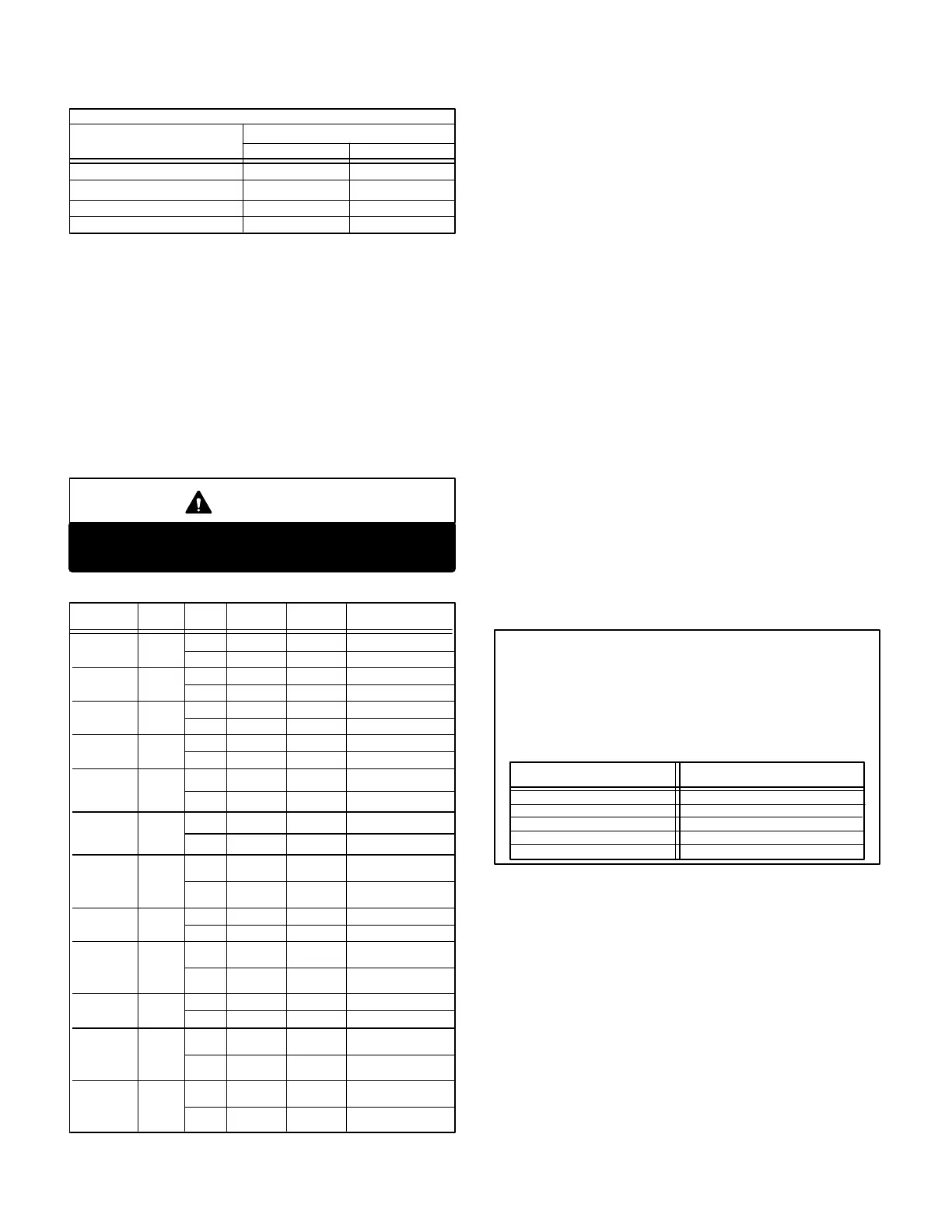
TABLE 7
MANIFOLD PRESSURE ALL GCS16 SERIES UNITS*
Stage
Operating Pressure (outlet) in. W.C.
First (Low Fire)
Second (High Fire) 3.7 + 0.3
Natural L.P.
5.5 + 0.3
10.5 + 0.5
1.6 + 0.2
*Maximum inlet pressure for all gas valves is 13" W.C.
Single heat exchanger models.
First (Low Fire)
Second (High Fire)
Dual heat exchanger models.
3.7 + 0.3 10.5 + 0.5
3.7 + 0.3 10.5 + 0.5
2- While waiting for the unit to stabilize, notice the flame.
The flame should be stable without flashback and
should not lift from the burner heads. Natural gas
should burn basically blue with some clear streaks.
L.P. gas should burn mostly blue with some clear yel
low streaks.
3- After allowing the unit to stabilize for five minutes, re
cord the manifold pressure and compare to the values
given in table 7.
CAUTION
Disconnect heating demand as soon as an accu
rate reading has been obtained.
TABLE 8
Unit Fuel Stage
Input
Btuh
Output
Btuh
Input
(ft.
3
/hr.)
GCS16
1853-235
2553235
2753235
1853-330
Nat.
L.P.G.
1st
2nd 235,000
116,000
188,000
145,000
Nat.
1st
2nd 330,000
159,900
257,400
205,000
GCS16
1853-235
2553235
2753235
1853-330
1st
2nd 235,000
131,200
188,000
164,000
1st
2nd 330,000
189,600
264,000
237,000
L.P.G.
GCS16
823-135
Nat.
GCS16
823-135
L.P.G.
GCS16
953-200
Nat.
GCS16
953-200
L.P.G.
GCS16
1353-270
1603270
Nat.
L.P.G.
GCS16
1353-270
1603270
GCS16
2553470
2753470
3003470
Nat.
GCS16
2553470
2753470
3003470
L.P.G.
1st
2nd
1st
2nd
1st
2nd
1st
2nd
1st
2nd
1st
2nd
1st
2nd
1st
2nd
84,000
135,000
66,500
106,000
95,000
130,000
76,000
103,000
126,000
200,000
98,000
160,000
126,000
175,000
98,000
142,000
170,000
270,000
132,500
216,000
170,000
236,250
132,500
192,500
240,000
470,000
232,000
376,000
328,000
470,000
262,400
328,000
F-Proper Gas Flow
To check for proper gas flow to burners, determine Btuh in
put from the unit rating plate or table 8. Divide this input rat
ing by the Btuh per cubic foot of available gas. Result is the
number of cubic feet per hour required. Determine the flow
of gas through gas meter for two minutes and multiply by
30 to get the hourly flow of gas to the burners.
NOTE - To obtain accurate reading, shut off all other
gas appliances connected to meter.
G-High Altitude Derate
Units With Adjustable Regulator Only
(Honeywell Gas Valve)
The maximum input may be reduced by up to 20 percent on
A.G.A. units equipped with adjustable (Honeywell) gas valves
and operating on natural gas. See table 9.
To derate the unit use the following instructions. If high alti
tude conditions are present, also follow the instructions in
table 9.
Derate Procedure:
1- Check manifold pressure at the gas valve pressure
tap with unit operating at high fire (2nd stage).
2- To reduce maximum input, turn regulator adjusting
screw (figure 26) counterclockwise.
3- Re-check manifold pressure.
TABLE 9
If the heating value of the gas does not exceed the values listed in
this table, derating of unit is not required. Should the heating value
of the gas exceed the table values, or if the elevation is greater than
6,000 ft. above sea level, it will be necessary to derate the unit. Len
nox requires that derate conditions be 4 percent per thousand feet
above sea level. Thus at an altitude of 4000 feet, if the heating value
of the gas exceeds 1000 Btu/cubic ft., the unit will require a 16 per
cent derate.
HIGH ALTITUDE DERATE
Elevation Above
Sea Level (Feet)
Maximum Heating
Value (Btu/cubic ft.
5001-6000
4001-5000
3001-4000
2001-3000
Sea Level - 2000
900
950
1000
1050
1100
H-Inshot Burner
Air shutters are factory set for maximum air and cannot be
adjusted. Air shutters should always be fully open. Always
operate unit with access panel in place. A peep hole is fur
nished in the heating access panel for flame viewing. The
flame should be blue with yellow streaks.
Figure 41 shows how to remove burner assembly.
1- Turn off power to unit and shut off gas supply.
2- Remove screws as shown in figure 41.
3- Slide each burner off its orifice.
4- Clean and reassemble (reverse steps 1-3).
5- Be sure to secure all wires and check plumbing.
 Loading...
