Page 12
2
3
4
6
7
4
7
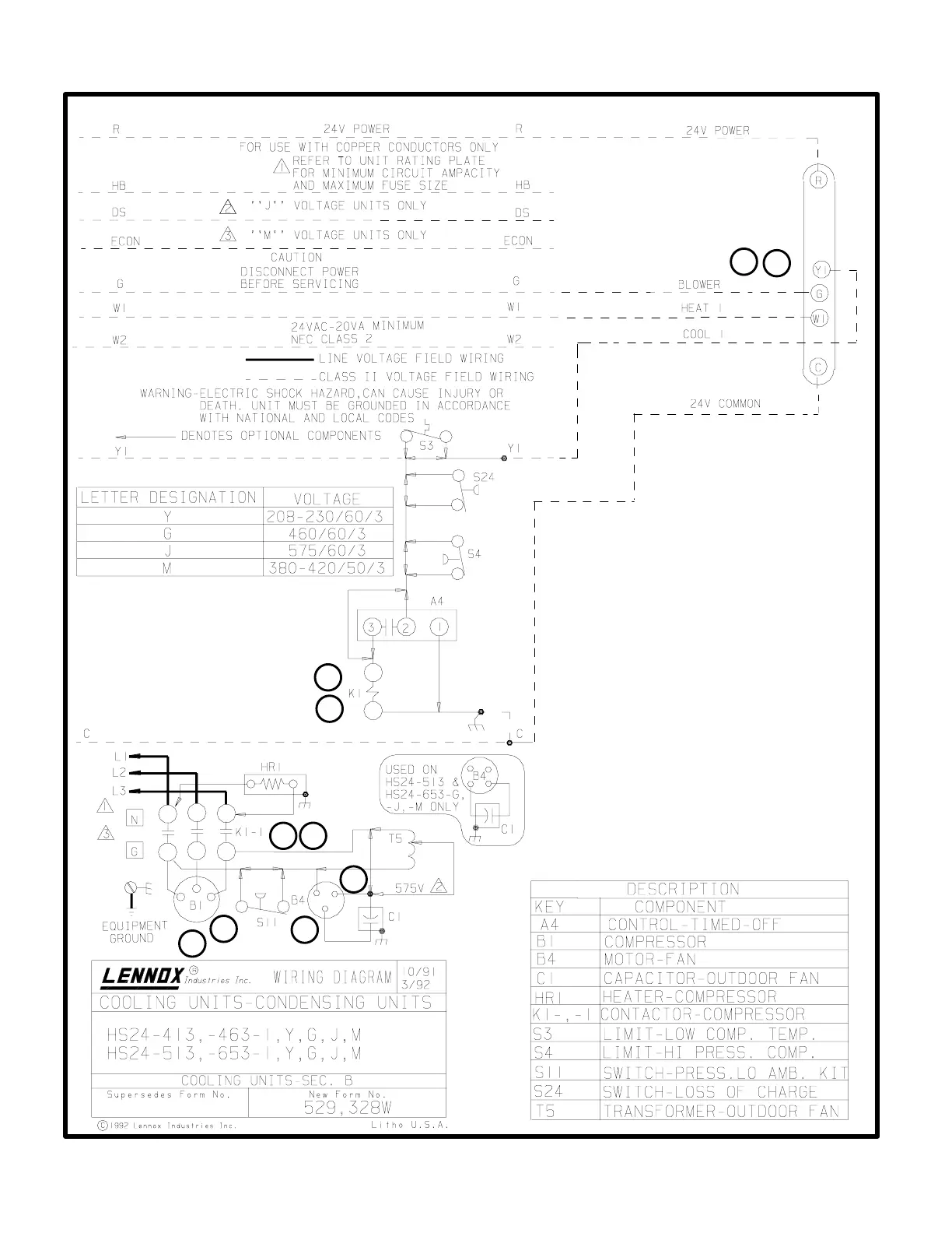
OPERATING SEQUENCE
B-HS24 (Y, G and J Voltage) Operation Sequence
This is the sequence of operation for HS24 Y, G and J
voltage units. The sequence is outlined by numbered
steps which correspond to circled numbers on the adjaĆ
cent diagram.
NOTE-The thermostat used may be electromechaniĆ
cal or electronic.
Cooling:
1- Cooling demand initiates at Y1 in the thermostat.
2- Compressor contactor K1 is energized
3- K1-1 N.O. closes energizing terminal C" of compressor
(B1) and condenser fan motor (B4).
4- Compressor (B1) and condenser fan motor (B4)
begin immediate operation.
End of Cooling Demand:
5- Cooling demand is satisfied.
6- Contactor K1 is deĆenergized.
7- K1-1 opens and compressor (B1) and condenser fan
motor (B4) are deĆenergized and stop immediately.
7
1
5
S1 THERMOSTAT
THREE PHASE OPERATING SEQUENCE
 Loading...