EasyManuals Logo

Lennox KCC Series User Manual

Lennox KCC Series
51 pages
To Next Page IconTo Next Page
To Previous Page IconTo Previous Page
Page #20 background imageLoading...
Page #20 background image
Page 20
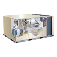
C-Blower Compartment
NOTE - Units equipped a Variable Frequency Drive (VFD)
are designed to operate on balanced, three-phase power.
Operating units on unbalanced three-phase power will re-
duce the reliability of all electrical components in the unit.
Unbalanced power is a result of the power delivery system
supplied by the local utility company. Factory-installed in-
verters are sized to drive blower motors with an equiva-
lent current rating using balanced three-phase power. If
unbalanced three-phase power is supplied; the installer
must replace the existing factory-installed inverter with an
inverter that has a higher current rating to allow for the im-
balance. Refer to the installation instructions for additional
information and available replacements.
The blower compartment in all units is located between
the evaporator coil and the condenser coil section. The
blower assembly is accessed by disconnecting the blower
motor .See Blower Access in the Operation/ Adjustment
section.
1-Blower Wheels
             
blower wheel.
2-Indoor Blower Motor B3
      
       
      
        
       

      
        

Operation and Adjustments
A-Three Scroll Compressor Voltage Phasing
Three phase scroll compressors must be phased
sequentially to ensure correct compressor and blower
rotation and operation. Compressor and blower are wired
    

 Observe suction and discharge pressures and

󰀨

      

marking.
 Disconnect all remote electrical power supplies.
 

at blower contactor or compressors.
 Make sure the connections are tight.
Discharge and suction pressures should operate at their

Supply Air Inverter Units - Units are equipped with a
phase monitor located in the control compartment. The



will turn red and the unit will not start. In normal operation
        
green.
B-Blower Operation
Initiate blower demand at thermostat according to
instructions provided with thermostat. Unit will cycle
       

 Blower operation is manually set at the thermostat
ON
blowers will operate continuously.
 AUTO
cycle with demand. Blowers and entire unit will be
󰀨OFF position.
C-Blower Access



 Loosen the reusable wire tie which secures the
blower wiring to the blower motor mounting plate.
 

 

location on the blower motor base using the wire tie.
 


Questions and Answers:

Question and Answer IconNeed help?

Do you have a question about the Lennox KCC Series and is the answer not in the manual?

Lennox KCC Series Specifications

General IconGeneral
BrandLennox
ModelKCC Series
CategoryAir Conditioner
LanguageEnglish

Related product manuals