Page 24
D-Optional Electric Heat Components
and capacities.
response to thermostat demand.
1-Contactors K15, K16
contactors located on the electric heat vestibule. All
contactors are equipped with a 24VAC coil. The coils in the
stage heating elements.
2-High Temperature Limits S15 (Primary)
+ +
++
+
+
++
The thermostat is not adjustable.
3-High Temperature Limit S20, S157, S158, S159, S160
& S161 (Secondary)
+ +
4-Terminal Strip TB2
TB2.
5-Terminal Strip TB3
Electric heat line voltage connections are made to terminal
heat vestibule. TB3 distributes power to the electric heat
components.
6-Heating Elements HE1 through HE6
The elements in 208/230V units are connected in a
connected in “Wye” arrangement. Each stage is energized
independently by the corresponding contactors located on
is provided by primary and redundant high temperature
7-Fuse F3
8-Unit Fuse Block F4
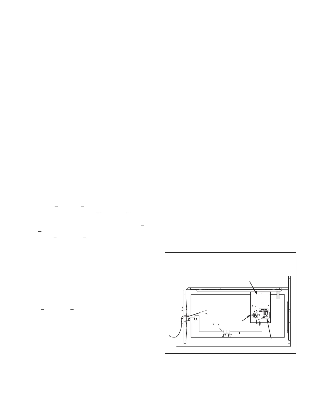
ELECTRIC HEAT CONTROL ASSEMBLY
1-Electric Heat Relay K9
All KCC series units with electric heat use an electric
ELECTRIC HEAT CONTROL ASSEMBLY
ELECTRIC HEAT
SECTION
DL2
ELECTRIC HEAT
CONTROL ASSEMBLY
K9
FIGURE 11
 Loading...