Page 41
dampers are closed and the supply air blower is operating.
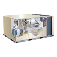
POWER EXHAUST FAN AND
BAROMETRIC RELIEF DAMPER INSTALLATION
POWER
EXHAUST FAN ASSEMBLY
(ORDERED SEPARATELY)
BAROMETRIC
RELIEF
P18
DAMPERS
FIGURE 27
Locate the A6 enthalpy control in the control area. The
Electric heater is available to automatically control the
minimum temperature in the gas burner compartment.
possible to the gas valve. It is wired in series with
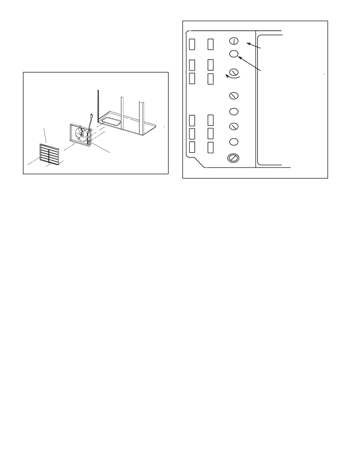
A6 ENTHALPY CONTROLLER
A
B
C
D
Open
Min
Pos
Free
Cool
DCV
EXH
EXH
Set
2V 10V
DCV
Max
2V 10V
DCV
Set
2V 10V
ADJUST POWER
EXHAUST FAN
SETPOINT
ENERGIZED WHEN
DAMPER POSITION
IS HIGHER THAN
EXHAUST FAN
SETPOINT
FIGURE 28
a
switch which opens on a temperature drop. The switch
is wired in series with 24V power and the combustion
air blower switch. When the temperature drops below
when the heating compartment temperature reaches
switch which opens on a temperature rise. The switch
tomatically resets when the heating compartment tem
switch which closes on a temperature drop. The switch
tric heater is energized. The switch automatically opens
K-Control Systems
All thermostat wiring is connected to TB1 located in the
control area. Each thermostat has additional control op
more detail.
L-Smoke Detectors A171 and A172
The smoke detectors can be installed in the supply air
supply and return air sections.
 Loading...