Page 6
VERTICAL VENTS USING METAL VENT PIPE
All LF24 unit heaters are listed as Category 1 appliances
for vertical vent installations.
1 − All LF24 unit heaters are to be used with NFPA− or
ANSI−approved chimneys or U.L.−listed type B−1
gas vents where applicable, as well as the
modifications and limitations listed in figure 2. Seal
single−wall vent material according to General
Recommendations and Requirements section.
2 − Keep the vent connector runs as short as possible
with a minimum number of elbows. Refer to the
current edition of ANSI Z223.1 or CSA−B149
installation compliance codes for maximum vent
and vent connector lengths. Horizontal run of the
vent connector from the combustion air inducer
outlet to the chimney/vent pipe cannot exceed the
values in table 6. Single−wall vent connectors shall
not be insulated.
TABLE 5
VENT CONNECTOR DIAMETERS
Model Number Connector Diameter
LF24−100,
LF24−115
LF24−145
4" (102mm)
LF24−175
LF24−200
LF24−230
LF24−250
LF24−300
5" (127mm)
LF24−345
LF24−350
LF24−400*
6" (152mm)
* On LF24−400 models, a minimum 6" (162mm) straight section must be
placed between the flue transition and the first elbow of the vent
.
A single 3" (76 mm), 4" (102mm), or 5" (127 mm)
elbow is equivalent to 5 feet (1.53 m) of vent pipe. A
single 6" (152mm) elbow is equivalent to 9 feet (2.75
m) of vent pipe.
Single−wall vent connector shall not be insulated.
3 − All LF24 models may be vented vertically as a single
appliance, or as a common vent with other gas−fired
appliances. In a common venting situation, vent
connectors for other appliances must be joined to
the vent at least 4" (102 mm) above the connected
LF24 connection. When common venting with
another LF24 unit, maintain at least a 4" (102 mm)
vertical separation between the vent connectors.
4 − Clearance to combustible material is 6" (152mm) for
single−wall vent material except where a listed
clearance thimble is used. Clearance to
combustible material for type B−1 vent or
factory−built chimney is per manufacturer’s
instructions.
5 − The vent connector must be supported with hangers
no more than three feet (1 m) apart to prevent
movement after installation. All horizontal vent
connector runs must have a slope up to the vertical
vent of at least 1/4" per foot (1mm per 50mm).
6 − All vertical vents must be terminated with a UL−listed
(or other equivalent agency) vent cap or rain shield
assembly unless local codes permit otherwise.
7 − The vent pipe must extend at least 3 feet (1m) above
the highest point where it passes through a roof of a
building. The vent must also extend at least two feet
higher than any part of a building within a horizontal
distance of 10 feet (3.05 m) unless otherwise
specified by the ANSI Z223.1 or CSA−B149
installation compliance codes. The vent must
extend at least 5 feet (1.53 m) above the highest
connected equipment flue collar.
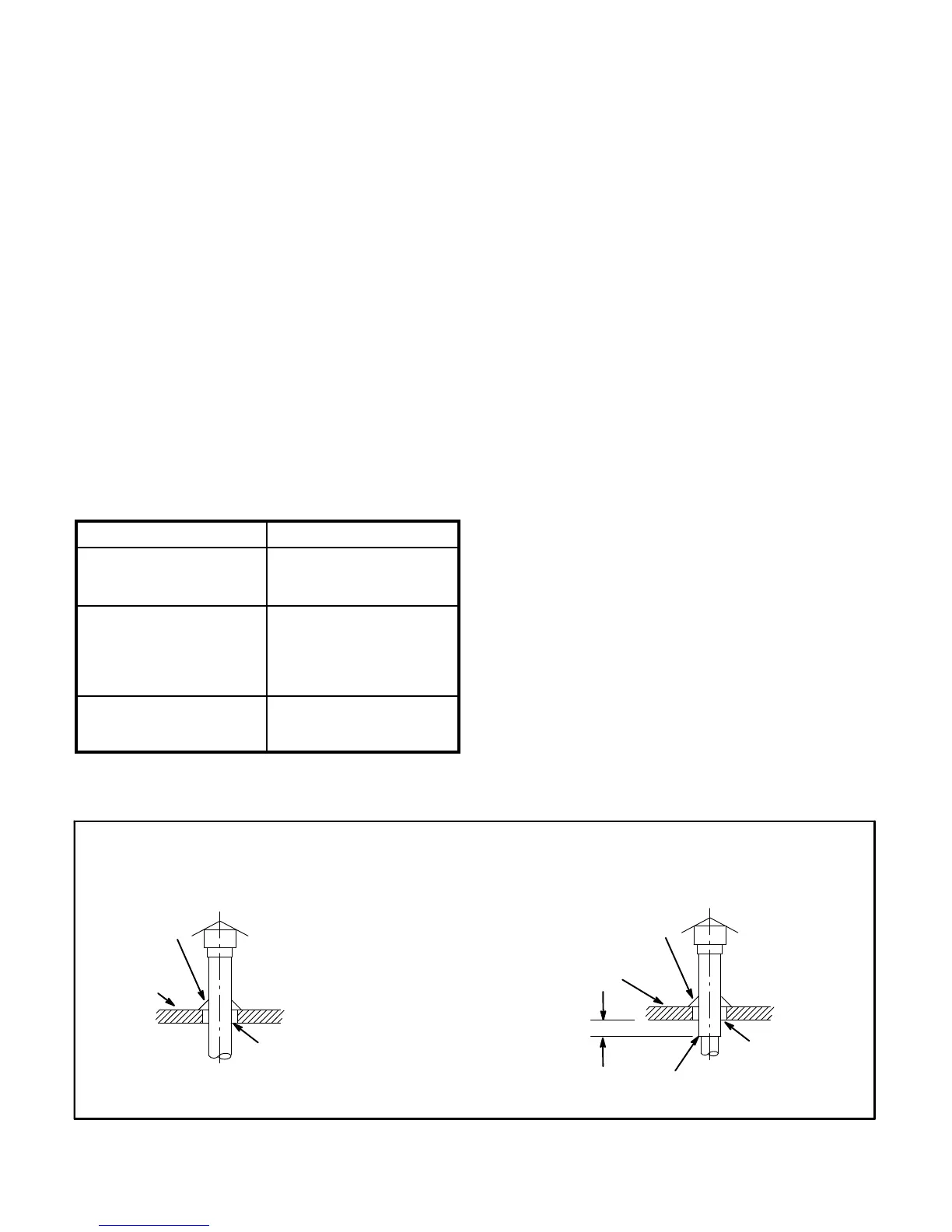
FIGURE 2
VENT TERMINATION ON SINGLE−WALL VERTICAL VENT RUNS
SINGLE−WALL VENT PIPE WITH
SINGLE−WALL TERMINATION
SINGLE−WALL VENT PIPE WITH
DOUBLE−WALL (TYPE B−1) TERMINATION
ROOF FLASHING
ROOF PITCHED
FROM 0" TO 45"
2" CLEARANCE
THIMBLE
CLEARANCE TO BE
AS SPECIFIED ON
TYPE B" VENT PIPE.
12" MAX
ROOF FLASHING
ROOF PITCHED
FROM 0" TO 45"
SEAL JOINT BETWEEN SINGLE−WALL VENT AND B" VENT TERMINATION
AND THE OPEN SPACE BETWEEN THE SINGLE WALL VENT PIPE AND
THE OUTER PIPE OF THE B" VENT TERMINATION.
 Loading...