Page 5
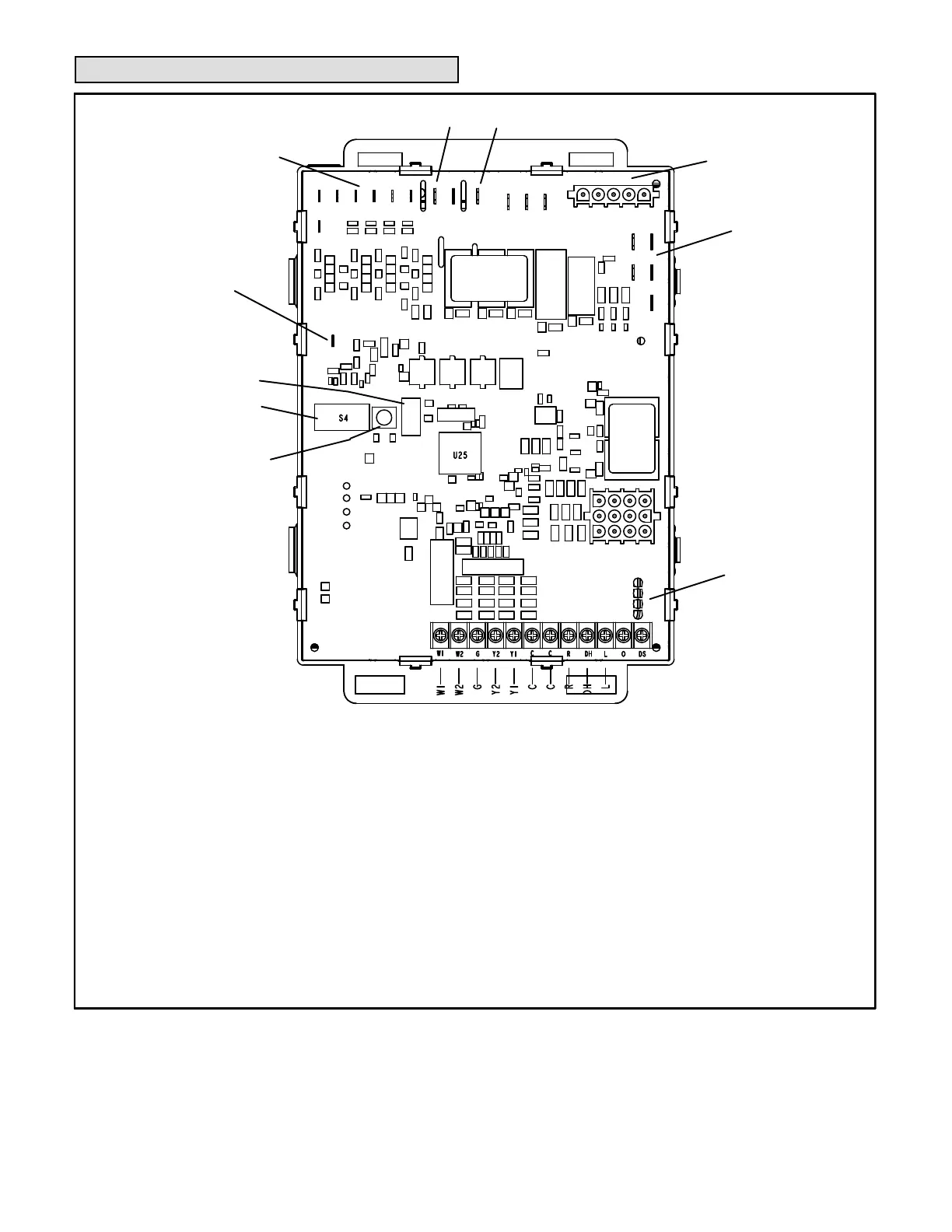
Integrated Ignition Control
FIGURE 3
THERMOSTAT CONNECTIONS (TB1)
1/4” QUICK CONNECT TERMINALS
HUM = UNPOWERED NORMALLY OPEN (DRY) CONTACTS
LI = 120 VAC INPUT TO CONTROL
ACC = 120 VAC OUTPUT TO OPTIONAL ACCESSORY
NEUTRALS = 120 VAC NEUTRAL
3/16” QUICK CONNECT TERMINALS
FLAME SENSE SIGNAL
HI COOL 24VAC -
Used for normal cooling operation
HI HEAT 24VAC - Used for 60 second heating operation if indoor
blower is running during heat deman
d
LO HEAT 24VAC -
Used for normal heat operation
PARK
PARK
COMMON 24VAC
Flame Sense
S4 DIP Switches
24VAC Indoor
Blower Terminals
HUM
ACC
Ignitor and Combustion
Air Inducer
Neutrals
On Board Links
LED
Diagnostic Push
Button
LO COOL 24VAC - Continuous fan see table 7
W1 = Heat Signal From Single Stage T-Stat
W2 = Not Used
Y1 = Not Used
Y2 = Cool Signal From Single Stage T-Stat
G = Manual Fan From T-Stat
C = T-Stat Signal Ground Connected To Transformer
Ground (TR) And Chasis Ground (GRD)
R = Class 2 Voltage To T-Stat
L = Not Used
DH = Not Used
DS = Not Used
 Loading...