Page 6
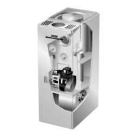
Figure 4
Beckett Oil Burner Nozzle Adjustment
To Adjust Nozzle
Burner must be removed from
furnace for this procedure.
1−Loosen screw.
2−Slide entire nozzle/electrode assembly back and forth until
nozzle just touches gauge.
1
2
gauge
Venting
WARNING
Combustion air openings in front of the furnace must
be kept free of obstructions. Any obstruction will
cause improper burner operation and may result in
a fire hazard.
WARNING
The barometric damper shall be in the same atmo-
spheric pressure zone as the combustion air inlet to
the furnace. Deviation from this practice will cause
improper burner operation and may result in a fire
hazard.
CAUTION
Do not store combustible materials near the furnace
or supply air ducts. The material (such as paint, mo-
tor oil, gasoline, paint thinner, etc.) may ignite by
spontaneous combustion creating a fire hazard.
WARNING
This furnace is certified for use with type L" vent.
B" vent must not be used with oil furnaces.
NOTE − Oil burning equipment may be vented into an ap-
proved masonry chimney or type L vent. (Type L vent is
similar in construction to type B gas vent except it carries a
higher temperature rating and is constructed with an inner
liner of stainless steel rather than aluminum).
Prior to installation of unit, make a thorough inspection of the
chimney to determine whether repairs are necessary. Make
sure the chimney is properly constructed and sized accord-
ing to the requirements of the National Fire Protection Asso-
ciation. The smallest dimensions of the chimney should be
at least equal to the diameter of the furnace vent connector.
Make sure the chimney will produce a steady draft sufficient
to remove all the products of combustion from the furnace. A
draft of at least .04" w.c. (9.9 Pa) is required during burner
operation.
1 − Local building codes may have more stringent installa-
tion requirements and should be consulted before
installation of unit.
2 − The vent connector should be as short as possible to
do the job.
3 − The vent connector should not be smaller than the out-
let diameter of the vent outlet of the furnace.
4 − Pipe should be at least 24 gauge galvanized.
5 − Single wall vent pipe should not run outside or through
any unconditioned space.
6 − Chimney should extend 3 feet (0.9 m) above highest
point where the vent passes through the roof, and 2
feet (0.6 m) higher than any portion of a building within
a horizontal distance of 10 feet (3 m).
7 − The vent must not pass through a floor or ceiling.
Clearances to single wall vent pipe should be no less
than 6" (152 mm); more if local codes require it.
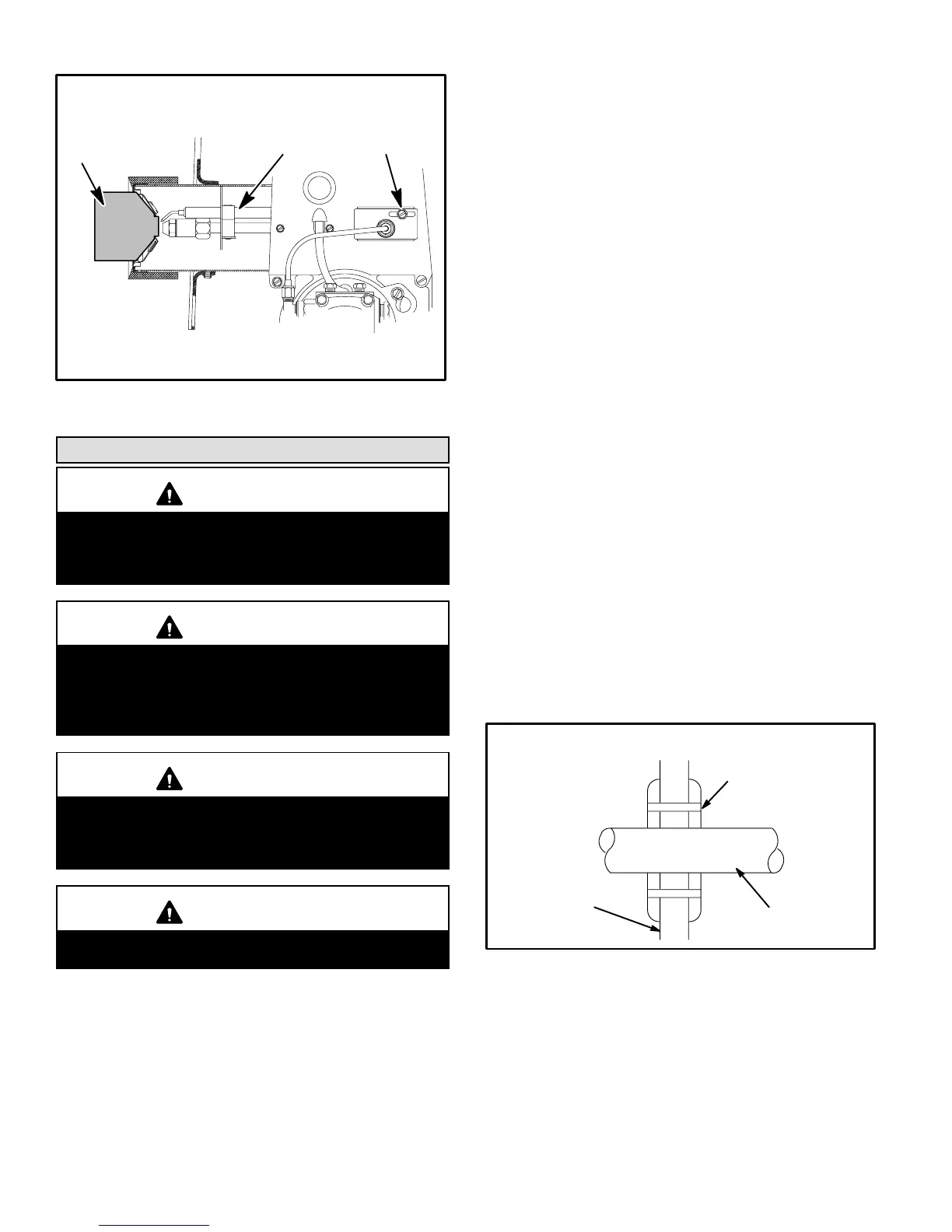
8 − The vent may pass through a wall where provisions
have been made for a thimble as specified in the Stan-
dards of the National Board of Fire Underwriters. See fig-
ure 5.
Wall Thimble
Figure 5
thimble
vent pipe
combustible
wall
9 − The vent pipe should slope upward toward the chim-
ney on horizontal run at least 1/4 inch (6 mm) to the
foot (0.3 m) and should be supported by something
other than the furnace, such as isolation hangers. See
figure 6.
 Loading...