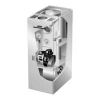
Page 7
Front Flue / Masonry Chimney
Rear Flue / Masonry Chimney
clean out
clean out
liner
masonry
chimney
barometric
control*
(in either location)
clean out
clean out
liner
masonry
chimney
Figure 6
*Barometric control may be installed in either vertical or hori-
zontal section of flue pipe within 18" of flue outlet of furnace.
barometric
control*
(in either location)
10− Extend the vent pipe into the chimney so that it is flush
with the inside of the vent liner. Seal the joint between
the pipe and the liner.
11− The furnace shall be connected to a factory built chim-
ney or vent complying with a recognized standard, or
masonry or concrete chimney lined with a lining mate-
rial acceptable to the authority having jurisdiction.
12− When two or more appliances vent into a common
vent, the area of the common vent should not be less
than the area of the largest vent or vent connection
plus 50% of the area of the additional vent or vent con-
nection. Chimney must be able to sufficiently vent all
appliances operating at the same time.
13− The vent pipe shall not be connected to a chimney
vent serving a solid fuel appliance or any mechanical
draft system.
14− All unused chimney openings should be closed.
15− All vent pipe run through unconditioned areas or out-
side shall be constructed of factory built chimney sec-
tions. See figure 7.
16− Where condensation of vent gas is apparent, the vent
should be repaired or replaced. Accumulation of con-
densation in the vent is unacceptable.
17− Vent connectors serving this appliance shall not be
connected into any portion of mechanical draft sys-
tems operating under positive pressure.
18− Keep the area around the vent terminal free of snow,
ice and debris.
NOTE − If vent pipe needs to exit from side of cabinet,
use the pilot hole (located on either side of the unit) to
cut a 6" (152 mm) round hole. Attach finishing plate
(provided) with four sheet metal screws to cover rough
edges.
Front Flue / Factory−Built Chimney
Rear Flue / Factory−Built Chimney
Figure 7
*Barometric control may be installed in either vertical or hori-
zontal section of flue pipe within 18" of flue outlet of furnace.
drain for
condensate
factory
built
chimney
drain for
condensate
factory
built
chimney
barometric
control*
(in either location)
barometric
control*
(in either location)
 Loading...