Do you have a question about the Lenord+Bauer MotionLine GEL 8230 and is the answer not in the manual?
Crucial safety guidelines for operating the MotionController to prevent harm and damage.
Defines the intended industrial application and usage of the MotionController for safe and effective operation.
Details the hardware differences between GEL 8230, 8231, 8235, and 8236 MotionController models.
Outlines the display capabilities, main windows, and menu access features of the MotionController.
Explains the manual's structure, symbols, and guidelines for user measuring units.
Lists all components included in the MotionController package, such as hardware, software, and accessories.
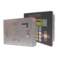
Details the physical installation procedures for different MotionController models (GEL 8230/8231 and GEL 8235/8236).
Provides step-by-step instructions for safely removing the MotionController from its installation.
Explains how to install functional or field bus extension modules onto the MotionController.
Provides essential advice for correct wiring to ensure electromagnetic compatibility (EMC) and secure connections.
Illustrates the pin assignments and coding for all input and output connectors on the MotionController.
Presents a detailed diagram of all connectors and their pin configurations for easy reference.
Explains the electrical power supply requirements and connection options for the MotionController and peripherals.
Details the configuration and pinout for the RS 232 C and RS 422/485 serial communication interfaces.
Describes the CAN bus interfaces, including termination, DIP switches, and bus configuration.
Covers connecting SSI and incremental encoders, including power supply and signal types.
Explains the functionality and status indication of the digital input terminals.
Details the configuration for measuring analog signals (current/voltage) via input I6.
Describes the specific analog inputs for PT100 temperature sensors on GEL 8231/8236 models.
Explains the digital and analog output terminals, their specifications, and status indicators.
Identifies and explains the functionality of each button on the MotionController's front panel keypad.
Explains the layout and informational elements shown on the MotionController's display screen.
Describes the navigation and structure of the MotionController's operating windows and menu system.
Covers initial setup, power application, and startup display of the MotionController.
Provides detailed instructions for updating the MotionController's operating system software via LingiMon.
Introduces system parameters, their types, and general configuration principles.
Explains how to reset parameters to default values or load saved configurations.
Covers fundamental application-specific configurations like general settings, PLC, and serial communication.
Details settings for analog inputs, including state, gate time, and PT100 specific configurations.
Configuration for CAN bus operation, including Master/Slave modes, CAN Link, and Object/PDO settings.
Configuration for various actual value input types, including Incremental, SSI, CAN bus, Virtual, and Analog.
Configuration for nominal value outputs, including Analog, CAN bus, Signals, and Stepper motor types.
Detailed configuration for up to six axes, including control modes, feedback control, and ramps.
Provides physical dimensions and mounting information for GEL 8230/8231 models.
Lists detailed technical specifications for the MotionController, including electrical, communication, and environmental data.
Explains the LB2 protocol, its applications, and transmission settings.
Details the format of LB2 protocol messages, including headers, data, and check bytes.
Lists and explains the various transmission and function error codes used in the LB2 protocol.
Describes the standard and extended functions available within the LB2 protocol.
Introduces the Paraminator III software for PC-based configuration of MotionController parameters.
Details how to connect, read, modify, and save parameters using the parameter editor software.
| Category | Controller |
|---|---|
| Series | MotionLine |
| Type | GEL 8230 |
| Manufacturer | Lenord+Bauer |
| Input Voltage | 24 V DC |
| Protection Class | IP65 |
| Communication Interface | CANopen |
| Housing Material | Aluminum |
| Weight | 0.2 kg |