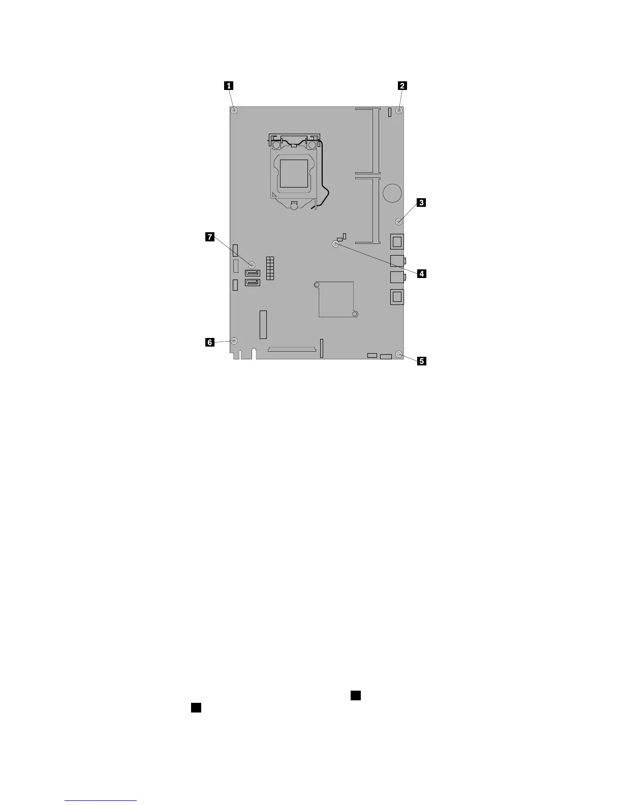
Figure40.Removingthesevenscrewsthatsecurethesystemboardtothemainbracket
13.Placethenewsystemboardintothechassisandalignthescrewholeswiththoseinthechassis.
14.Reinstallthesevenscrewsthatsecurethesystemboardtothemainbracket.
15.ReinstalltherearI/Oassembly.See“ReplacingtherearI/Oassembly”onpage99.
16.Reinstallthebattery.See“Replacingthebattery”onpage111.
17.Reinstallthememorymodules.See“Installingorreplacingamemorymodule”onpage113.
18.Reinstallthemicroprocessor.See“Replacingthemicroprocessor”onpage106.
19.Reinstalltheheatsinkassembly.See“Replacingtheheatsinkassembly”onpage104.
20.Reinstallthesystemboardshield.See“Removingandreinstallingthesystemboardshield”onpage101.
21.Reconnectallcablesthatweredisconnectedfromthesystemboard.See“Locatingpartsonthe
systemboard”onpage86
.
22.Goto“Completingthepartsreplacement”onpage124.
Thefailingsystemboardmustbereturnedwithamicroprocessorsocketcovertoprotectthepinsduring
shippingandhandling.
Toinstallthemicroprocessorsocketcover,dothefollowing:
1.Releasetheleversecuringthemicroprocessorretainerandopentheretainertoaccessthe
microprocessor.
2.Graspthemicroprocessoronthesidesandliftitstraightupandoutofthesocket.Donottouchthe
contactsonthemicroprocessorsocket.
3.Notetheorientationofthesocketcover.Alignthenotches1onthemicroprocessorsocketcover
withthealignmentkeys2onthemicroprocessorsocket.Installonesideofthesocketcoverinto
themicroprocessorsocket.
118ThinkCentreEdgeHardwareMaintenanceManual

 Loading...