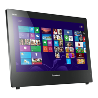
11.Removeallthe15screwsthatsecurethecomputermainbrackettothefrontbezel.
Figure44.Removingallthe15screwsthatsecurethecomputermainbrackettothefrontbezel
12.Notethelocationsofallcableconnectionsthatpreventyoufromliftingthecomputermainbracket,and
disconnectallcables.See“Locatingpartsonthesystemboard”onpage86.
13.Removetheintegratedcamera.See“Replacingtheintegratedcamera”onpage116
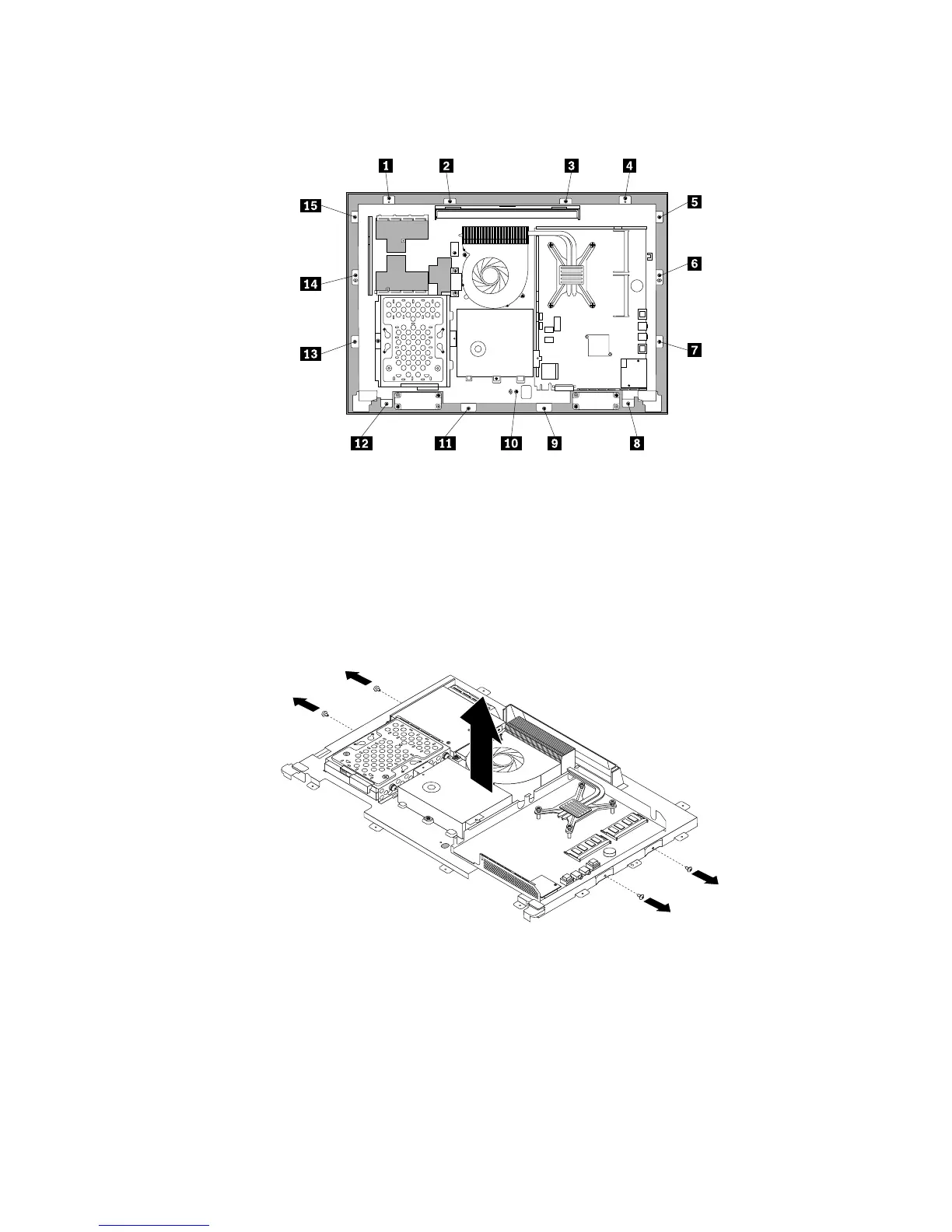
14.Liftthecomputermainbracketoffthefrontbezel.
15.RemovethefourscrewsthatsecurethechassistotheLCDpanel,andthenliftthechassisoutof
thecomputertogetassesstotheLCDpanel.
Figure45.RemovingthefourscrewsthatsecuretheLCDpanel
16.PlacethecomputerchassisoverthenewLCDpanelsothatthefourscrewholesalignwiththoseinthe
chassis.ReinstallthefourscrewstosecuretheLCDpaneltothechassis.
17.PositionthecomputermainbracketovertheLCDpanel.Makesurethescrewholesinthecomputer
mainbracketalignwiththoseinthefrontbezel.
18.Reinstallallthe15screwsthatsecurethecomputermainbrackettothefrontbezel.
Chapter9.ReplacingFRUs121

 Loading...