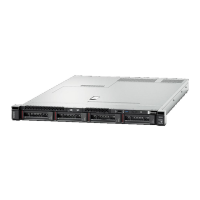
Figure 35. Flash power module installation
Step 1. Orient the flash power module with the cable side facing the RAID adapter; then, feed the cable up
through the flash power module holder.
Step 2. Slide the flash power module into the holder.
Step 3. Connect the flash power module cable to its connector on the RAID adapter. The connector is
keyed. Press the cable into the connector until the connector retaining clip snaps in place.
Step 4. Route the flash power module cable through the notch in the holder; then, press the flash power
module forward to seat it in the holder.
Attention: It is important to route the flash power module cable through the notch in holder to
prevent the cable from catching on the DIMM connector latches when the RAID adapter is installed
in a compute node.
Step 5. Install the RAID adapter in the compute node. (see
“Install a RAID adapter” on page 52 for
instructions).
After you install the flash power module, complete the following steps:
1. Install the RAID adapter in the compute node. (see
“Install a RAID adapter” on page 52).
Remove the 2.5-inch drive backplane
Use this information to remove the 2.5-inch drive backplane.
Before you remove the 2.5-inch drive backplane, complete the following steps:
1. Read “Installation Guidelines” on page 28 to ensure that you work safely.
2. Carefully lay the compute node on a flat, static-protective surface, orienting the compute node with the
bezel pointing toward you.
3. Remove the compute node cover (see
“Remove the compute node cover” on page 32 for instructions).
Notes:
Chapter 3. Compute node hardware setup 57
 Loading...
