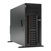
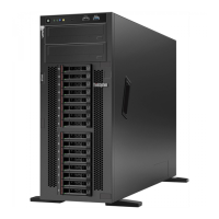
Rear view of server models with a fixed power supply
Figure 7. Rear view of server models with a fixed power supply
Table 4. Components on the rear of server models with a fixed power supply
Callout Callout
1 Fixed power supply
2 USB 2.0 connectors (2)
3 USB 3.0 connectors (2) 4 XClarity Controller network connector
5 USB 2.0 connectors (2) 6 Ethernet connectors (2)
7 VGA connector
8 NMI button
9 Serial-port-module slot 10 PCIe slot 1
11 PCIe slot 2 12 PCIe slot 3
13 PCIe slot 4 14 PCIe slot 5
15 PCIe slot 6
1 Fixed power supply
Used to connect the power cord.
2 3 5 USB connectors
Used to attach a device that requires a USB 2.0 or 3.0 connection, such as a keyboard, a mouse, or a USB
flash drive.
4 XClarity Controller network connector
Used to attach an Ethernet cable to manage the system using XClarity Controller.
6 Ethernet connectors
Used to attach an Ethernet cable for a LAN. Each Ethernet connector has two status LEDs to help you
identify the Ethernet connectivity and activity. For more information, see “Rear view LEDs” on page 21.
Chapter 2. Server components 19

 Loading...


