16 Accessory Decoder LS 100/110
Programming address and settings through the
programming output of LZ100
Address and other settings of LS100/LS110 are stored in so
called “registers”, abbreviated “R”. These registers can be
imagined as a sort of notepad that can have new entries put on
them again and again. The written entries remain stored even
after the power is turned off.
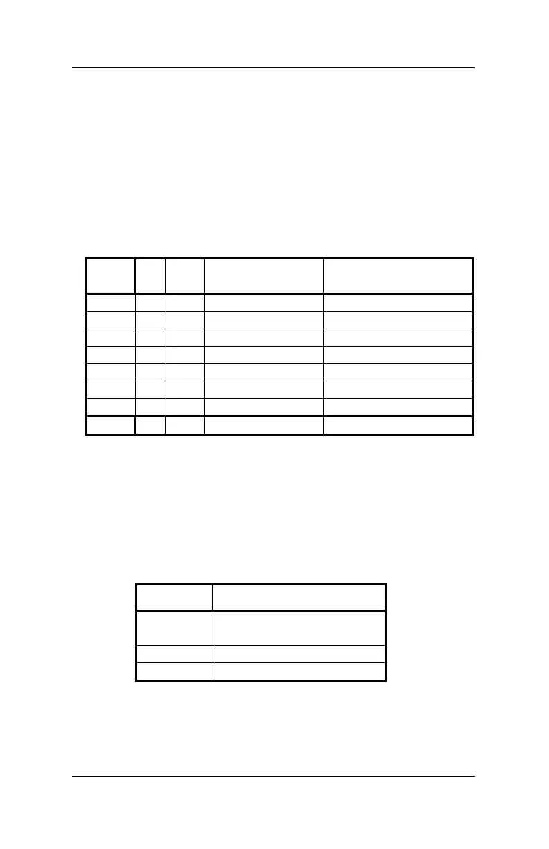
Assignment of registers
LS100/LS110 has 6 registers, that are used as follows:
Reg
AltC
V
used for allowed range of
values
1 1 513 address 1 - 256
2 3 515 settings output 1 0 - 15; 32; 33 - 47
3 4 516 settings output 2 0 - 15; 32; 33 - 47
4 5 517 settings output 3 0 - 15; 32; 33 - 47
5 6 518 settings output 4 0 - 15; 32; 33 - 47
7 7 519 version number 2.2
8 8 520 manufacturer ID 99
-
541 Configuration 128
Table 1: Assignment of registers
The value stored in R1 thus determines the address, the
‘number’ with which the connected function devices are
addressed.
R†2†to†5 behave the same: The values stored here determine
the settings of the outputs. From table 2 you see the values that
need to be entered for a desired setting of an output:
Value Setting
0 - 15 Pulse output, variable
pulse duration
32 Constant output
33 - 47 Flashing, variable rate
Table 2: Settings of the outputs
Values other than the ones listed are not allowed and will lead to
random results.