Power Station LV101 5
DIGITAL plus
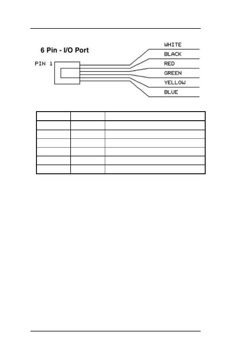
Figure 4: Wire connections for the LV101 6 pin -I/O port
Pin # Color Description
Pin 1 White
"C" Control Bus Connection
Pin 2 Black Ground
Pin 3 Red - RS-485
Pin 4 Green + RS-485
Pin 5 Yellow +12 volts
Pin 6 Blue
"D" Control Bus Connection
Installation considerations
There must not be a capacitor connected to the track for
interference control. A capacitor is only needed for conventional
operations to prevent radio interference. In DCC operation a
capacitor corrupts the data format and the error free data
transfer is disturbed.
It is normal for the Power Station to get warm during operation.
Ensure sufficient airflow around the Power Station to prevent the
internal safety circuit from activating during normal operations.
Never allow your layout to operate without supervision! If there is
an unnoticed short, the heat build-up could present a fire hazard!
Commom Rail Wiring
Normally both rails are gapped between power stations. This
provides complete isolation. However, in some scales there
exist locomotives that have pickups that are offset from each
other. For example many steam locomotives have power pickup
from one rail in the locomotive and the other rail in the tender.
 Loading...