8 Power Station LV101
needs of your layout.
The power blocks of several LV101 must necessarily have the
same polarity. Terminal J of one and terminal J of the next LV101
must therefore be connected to the same rail. Otherwise there will
be a short when passing a dividing gap. (See Figure 1)
Setting the track voltage
As previously mentioned, LV101 provides the ability to adjust the
track voltage level. This adjustment is useful if you for instance
want a lower output voltage for an N scale layout. You can select
an area between 11.5V and 22V.
To adjust the track voltage, you must open the LV101.
On the circuit board you find a DIP-switch.
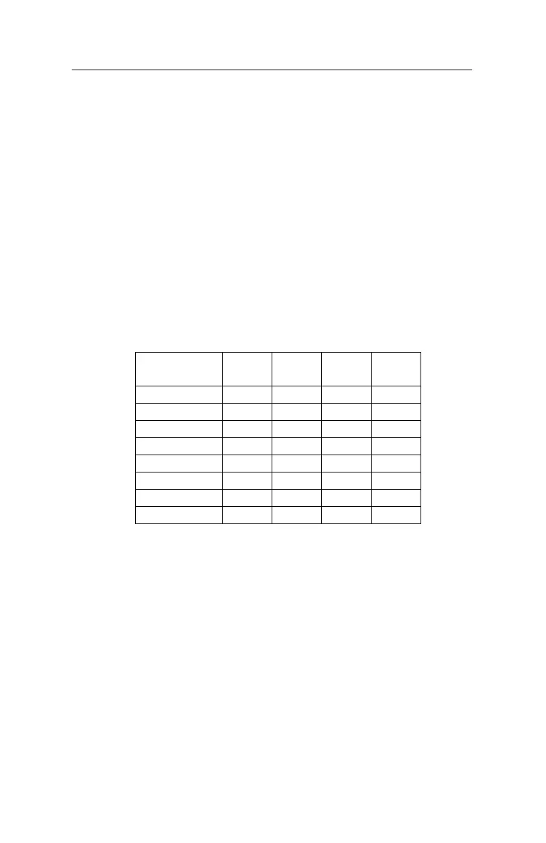
DCC Track
Voltage
SW 1 SW 2 SW 3 SW 4
11.5 Volts On On On N/A
13 Volts Off On On N/A
14.5 Volts On Off On N/A
16 Volts Off Off On N/A
17.5 Volts On On Off N/A
19 Volts Off On Off N/A
20.5 Volts On Off Off N/A
22 Volts Off Off Off N/A
Depending on the position of each of the 4 switches on this DIP-
switch, you get a different output voltage at terminals J and K.
The switch positions necessary to get a particular voltage are
also printed on LV101’s circuit board.
In order to reach the desired output voltage, you must use a
transformer with an output voltage that is as high as the desired
track voltage. But do not overdo it: The transformer voltage
should be matched as closely as possible to the desired track
voltage. Too high of a transformer voltage just generates
unnecessary heat loss in the power station, and this will lead to
premature triggering of the overload fuse, before the maximum
 Loading...