-UG +UG RB1 RB2 PE
1
2
3
(T1) (T2)
Pos. Name/
Meaning
Note
-UG +UG RB1 RB2 PE
1
2
3
(T1) (T2)
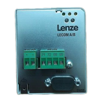
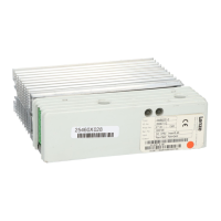
1 Brake unit D 8251/8252 brake module
D 8253 brake chopper
-UG +UG RB1 RB2 PE
1
2
3
(T1) (T2)
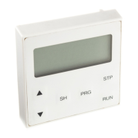
2 LED Display of the operating state
D green:
flashing, when voltage is
applied to terminals +U
G
,-U
G
D yellow:
- flashing, when brake unit is
in braking operation
- Display of faults:
see chapter 6, page 6-1
-UG +UG RB1 RB2 PE
1
2
3
(T1) (T2)
3 Connections D Voltage link:
+U
G
,-U
G
only 8251/8252 brake module:
D Thermostat: T1, T2
only 8253 brake chopper:
D Brake resistor: RB1, RB2
 Loading...