Electrical installation
Mounting steps
4
33
EDKRBD180R DE/EN/FR 2.0
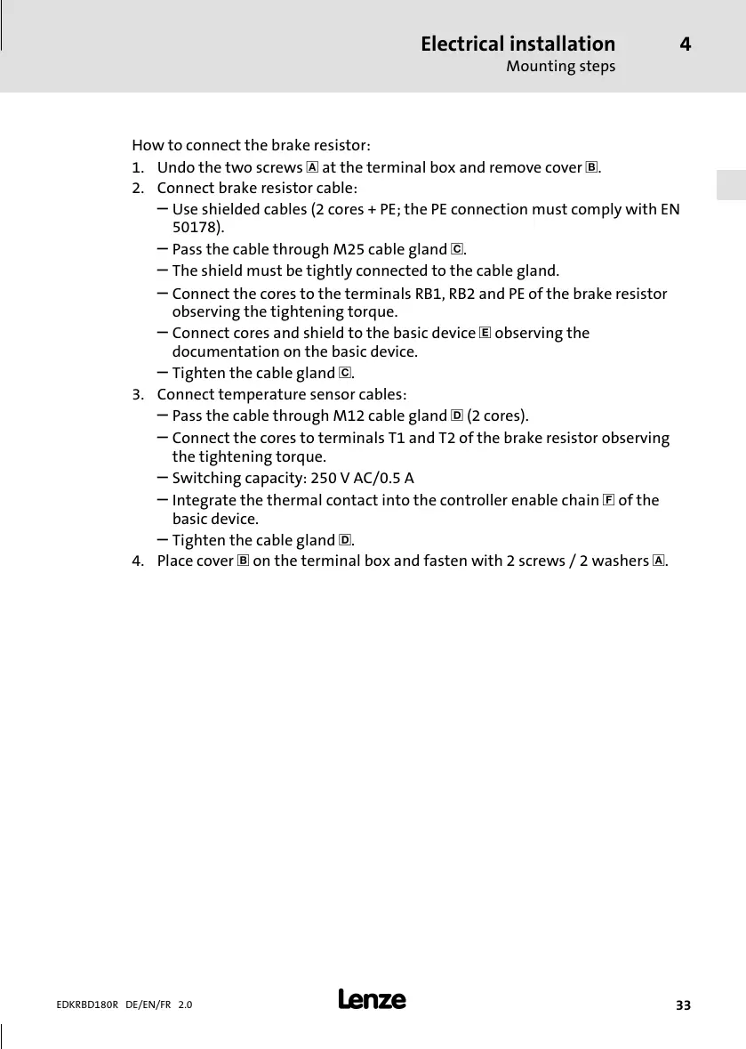
How to connect the brake resistor:
1. Undo the two screws at the terminal box and r emove cover .
2. Connect brake resistor cable:
–
Use shi elded cables (2 cores + PE; the PE connection must comply with EN
50178).
–
Pass the cable through M25 cable gland .
–
The shield must be tightly connect ed to the cable gland.
–
Connect the cores to the terminals RB1, RB2 and PE of the brake resistor
observing the tightening torque.
–
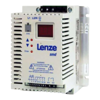
Connect cores and shield to the basic device observing the
documentationonthebasicdevice.
–
Tighten the cable gland .
3. Connect temperature sensor cables:
–
Pass the cable through M12 cable gland (2 cores).
–
Connect the cores to terminals T 1 and T2 of the brake resistor observing
the tightening torque.
–
Switching capacity: 250 V AC/0.5 A
–
Integrate the thermal contact into the controller enable chain of the
basic device.
–
Tighten the cable gland .
4. Place cover on the terminal box and fasten with 2 screws / 2 washers .
 Loading...