Electrical installation
Important notes
6
l
49
EDKRBG018R DE/EN/FR/ES/IT 7.0
6 Electrical installation
6.1 Important notes
( Stop!
Possible overheating of the brake resistor during operation
Inadequate heat dissipation during operation can cause the brake
resistor to overheat.
Possible consequences:
ƒ The brake resistor is destroyed.
ƒ The drive is not braked but coasts to a standstill.
Protective measures:
ƒ Always connect the thermal contact of the brake resistor.
ƒ Integrate the thermal contact into the overall equipment
monitoring apparatus in such a way that the supply of power to
the standard device is switched off if the brake resistor overheats
(e.g. switch−off by means of mains contactor control).
6.2 Connection data
Connection Cable gland Connection type Connection size Starting torque
RB1, RB2
(brake resistor)
M25 / M40
1)
Stud terminal M6
4 Nm
35.4 lb−in
PE (PE
conductor)
T1, T2
(thermal
contact)
M16 Tunnel terminal
0.75 ... 1.5 mm
2
18 ... 16 AWG
0.32 Nm
2.85 lb−in
1)
ERBG023D05K6, ERBG028D04K1
I Tip!
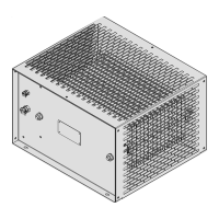
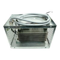
The brake resistor has two PE connections, one inside, the other
outside the housing.
ƒ If you use a brake resistor cable with PE conductor, lead this
through the cable gland and place the PE conductor inside.
ƒ If you use a separate PE cable, connect it outside.
 Loading...