Mechanical installation
Preparation
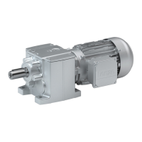
Attachment of gearboxes with hollow shafts and keyway
4
36
Lenze ¯ MA 12.0014 ¯ 5.1
Dismounting
( Stop!
¯ Before dismantling the machine shaft, mount an adequately
dimensioned load handling device at the gearbox.
¯ Ensure pretensioning of the drive mechanism, preventing the gearbox
from falling into the drive mechanism when it is loosened from the
plug−in shaft.
¯ When removing the hollow shaft via the housing, impermissibly great
forces may be generated.
¯ Tensioning of the hollow shaft causes a bearing failure and damage of
the gearbox housing.
1. Undo axial gearbox locking in the hollow shaft.
2. Remove/extract the gearbox from the motor shaft using an appropriate auxiliary
tool (Fig. 5).
Fig. 5 Disassembly of gearboxes with hollow shaft, with auxiliary tool
Auxiliary tool (recommended dimensions)
Æ d
H7
b ±0.1 c
8
c
9
c
10
d
1
±0.1 d
2
d
3
t −0.1 t
1
30 7.8 8 3 2 29.8 M10 18 33 5.5
35 *
9.8 7 3 5 34.8 M12 20 38 6
35
9.8 12 3 −−− 34.8 M12 −−− 38 6
40 11.8 12 4 −−− 39.8 M16 −−− 43 6
45 13.8 12 4 −−− 44.8 M16 −−− 48.5 7
50 13.8 12 5 −−− 49.8 M16 −−− 53.5 7
55 15.8 16 5 −−− 54.8 M20 −−− 59 7.5
60 17.8 16 5 −−− 59.8 M20 −−− 64.1 8
70 19.8 16 5 −−− 69.8 M20 −−− 74.1 8
80 21.8 20 5 −−− 79.8 M20 −−− 85.1 9
90 24.8 10 10 −−− 89.8 M20 72 95 11
100 27.8 15 10 −−− 99.8 M24 80 106 12
120 31.8 15 10 −−− 119.8 M24 80 127 15
Tab. 5 Dimensions in mm
* Auxiliary tool for gearbox size G50BB124
 Loading...